Supporting structure for mounting LED display screen

A technology of LED display screen and support structure, which is applied in the direction of supporting machines, machine tables/brackets, springs/shock absorbers, etc., which can solve the problems of display screen damage, labor cost, and display screen falling, so that it is not easy to shake and easy to use. Convenient and stable lifting effect

Pending Publication Date: 2021-12-24
江苏润江智汇显示科技有限公司
View PDF18 Cites 1 Cited by
  • Summary
  • Abstract
  • Description
  • Claims
  • Application Information

AI Technical Summary

Problems solved by technology

[0003] However, most of the existing LED display screens are not easy to install and operate, requiring multiple operators to install, thereby reducing work efficiency a

Method used


Image

  • Supporting structure for mounting LED display screen
  • Supporting structure for mounting LED display screen
  • Supporting structure for mounting LED display screen

Examples


Embodiment 1

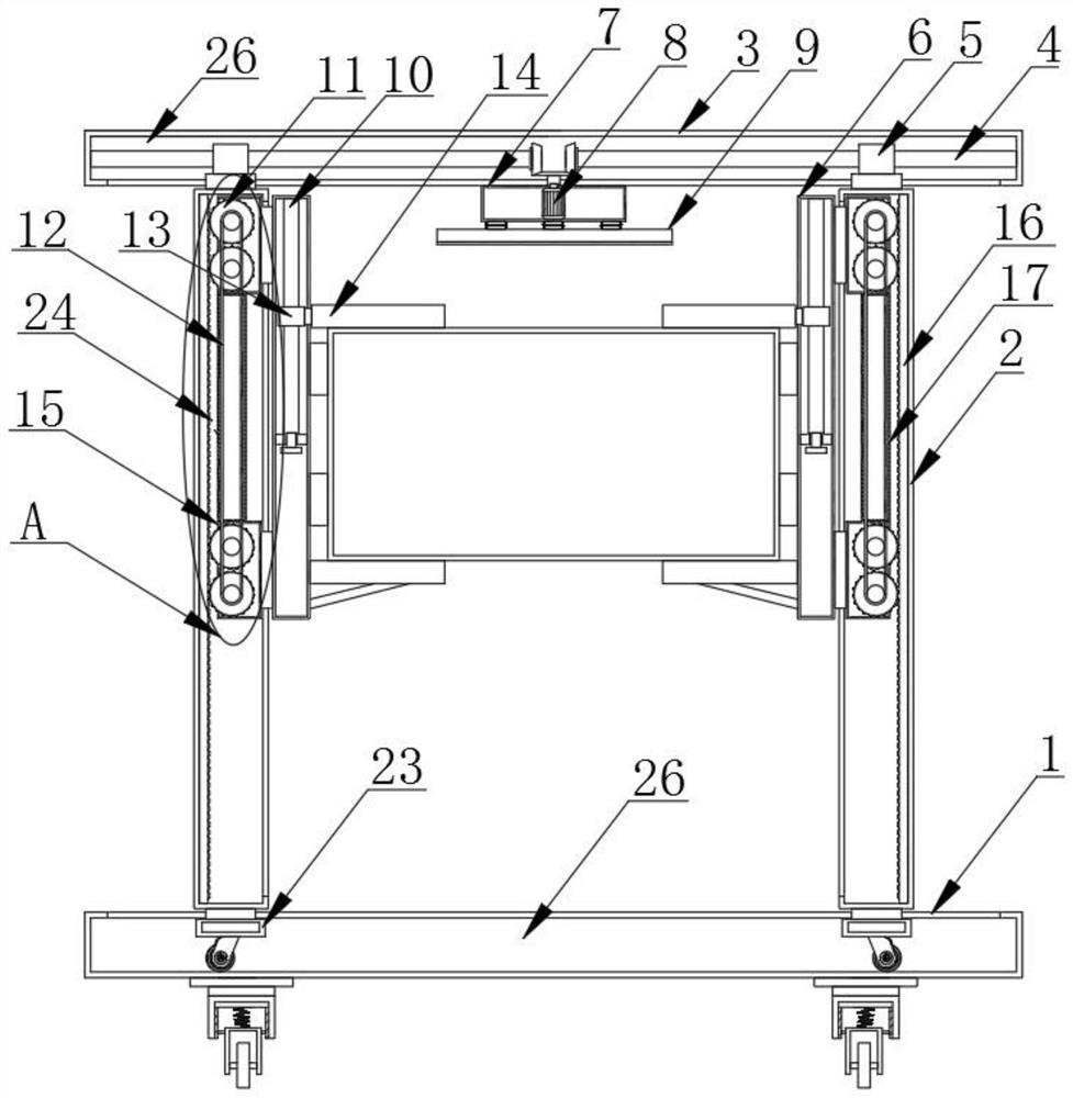
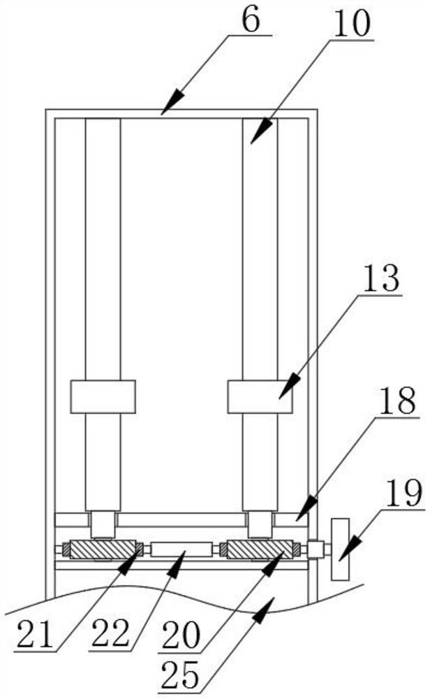
[0022] see Figure 1-4 , the present embodiment provides a support structure for LED display screen installation, including a fixed base 1, the top of the fixed base 1 is provided with a top plate 3, the inside of the top plate 3 is provided with a moving mechanism 26, between the fixed base 1 and the top plate 3 There are two support columns 2 symmetrically, and the inside of the two support columns 2 are provided with a lifting mechanism 24, and the two support columns 2 are symmetrically provided with two lifting plates 6, and the inside of the two lifting plates 6 are provided with a limit position. Institution 25.

[0023] Most of the existing supporting structures only limit and fix the LED display screen, which is inconvenient to adjust and fix it, so that it cannot be adjusted and fixed according to the LED display screens of different sizes.

[0024] In order to achieve the effect of adjusting LED display screens of different lengths, the moving mechanism 26 includes...

Embodiment 2

[0029] see Figure 1-2 , further improvements have been made on the basis of Example 1:

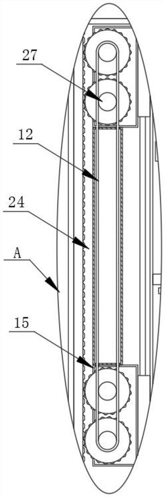
[0030] In order to achieve different installation work requirements, the lifting mechanism 24 includes two gear boxes 15, and the opposite ends of the two gear boxes 15 are welded through the connecting shell 17. Two gears 11 are arranged in the two gear boxes 15, and the two gears 11 A rotating block 27 is fixedly connected to one end of the rotating block 27, and the other end of the rotating block 27 is rotationally connected to the inner wall of the gear box 15. A belt 12 is arranged inside the connecting case 17, and both ends of the belt 12 run through the gear box 15 and are connected to the rotating block 27. , the outside of the support column 2 is provided with a drive motor, and the output end of the drive motor passes through the support column 2 and extends into the gear box 15, and one of the gears 11 is welded to the output end of the drive motor.

[0031]In this embodimen...


PUM


Abstract

The invention discloses a supporting structure for mounting a LED display screen, and relates to the technical field of building template conveying, the supporting structure comprises a fixed base, wherein a top plate is arranged at the top of the fixed base, moving mechanisms are arranged in the top plate, two supporting columns are symmetrically arranged between the fixed base and the top plate, and lifting mechanisms are arranged in the two supporting columns; two lifting plates are symmetrically arranged between the two supporting columns, and limiting mechanisms are arranged in the two lifting plates. The supporting structure for mounting the LED display screen has the advantages that the LED display screen can be conveniently mounted and operated, the purpose of limiting and fixing can be achieved only by rotating a rotating disc during use; and meanwhile, the LED display screens of different models and sizes can be limited and operated, and therefore, the situation that only the LED display screens of the same model can be mounted is avoided; and the LED display screens can be conveniently adjusted and lifted, and therefore, different mounting operation requirements are met.

Description

technical field [0001] The invention relates to the technical field of LED display screens, in particular to a support structure for LED display screen installation. Background technique [0002] With the continuous development of science and technology in my country in recent years, the display industry has made great progress, and LED displays have become an important part of various occasions. In order to facilitate the installation of LED displays, a LED display installation is required. supporting structure. [0003] However, most of the existing LED display screens are not easy to install and operate, requiring multiple operators to install, thereby reducing work efficiency and consuming a lot of labor. Cause damage to the display screen, so a support structure for LED display screen installation is designed here to solve the above problems. Contents of the invention [0004] The purpose of the present invention is to provide a support structure for installing LED d...

Claims


Application Information

Patent Timeline
IPC IPC(8): F16M11/42F16M11/04F16M11/18F16F15/067
CPCF16M11/42F16M11/046F16M11/18F16M11/04F16F15/067Y02E10/50
Inventor 夏梦曦李赟
Owner 江苏润江智汇显示科技有限公司
Why Eureka
Try Eureka