Remote sensing image change detection method combining posterior probability and spatial neighborhood information

A technology of neighborhood information and remote sensing images, applied in character and pattern recognition, instruments, computer parts, etc., can solve problems such as the inability to effectively solve the selection of change thresholds and insufficient spatial heterogeneity.

Pending Publication Date: 2021-12-24
SHANDONG JIANZHU UNIV
View PDF0 Cites 1 Cited by
  • Summary
  • Abstract
  • Description
  • Claims
  • Application Information

AI Technical Summary

Problems solved by technology

However, most of the methods do not fully consider the spatial heterogeneity, and cannot effectively solve the problem of selecting the change threshold of complex land cover types.

Method used


Image

  • Remote sensing image change detection method combining posterior probability and spatial neighborhood information
  • Remote sensing image change detection method combining posterior probability and spatial neighborhood information
  • Remote sensing image change detection method combining posterior probability and spatial neighborhood information

Examples


Embodiment 1

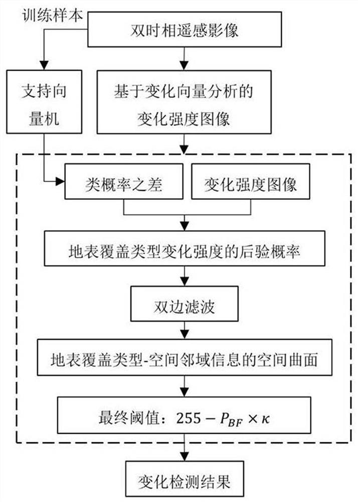
[0027] In step a), the variation intensity image is obtained by using the variation vector analysis (CVA) method.

Embodiment 2

[0029] In step a) through the formula Calculate the posterior probability I of the change intensity of the land cover type, where M is T 1 moment and t 2 The number of land cover types at any time, m is a constant, and the value range of m is between 1 and M, for T 1 The class probability of the mth land cover type at time instant, for T 2 The class probability of the mth land cover type at time instant, and Obtained by support vector machine, for T 1 the mth land cover type at time instant, for T 2 The mth land cover type at a time, N is the number of bands of the remote sensing image, n is a constant, and the value range of n is between 1 and N, for T 1 The remote sensing image pixel value of the nth band at the time, for T 2The remote sensing image pixel value of the nth band at the moment. The posterior probability of the change intensity of the land cover type in the study area is calculated according to the above formula.

Embodiment 3

[0031] Through the bilateral filtering formula, the spatial neighborhood information is integrated for the posterior probability of the intensity of land cover type change, and then the spatial surface of land cover type-spatial neighborhood information is constructed. Concrete step b) through the formula Calculate the land cover type corresponding to the pixel point p - the spatial surface value of the spatial neighborhood information where I bf is the spatial surface of land cover type-spatial neighborhood information, where is the sum of the normalized weights corresponding to the pixel point p, s is the space domain, r is the range domain, is a Gaussian decreasing function in the spatial domain, is the Gaussian decreasing function of the range domain, p is the pixel point in the center of the field, q is the pixel point adjacent to the pixel point p, ||p-q|| is the Euclidean distance between the pixel point p and the pixel point q, I p is the intensity value of ...


PUM


Abstract

The invention discloses a remote sensing image change detection method combining posterior probability and spatial neighborhood information. The method comprises the following steps: acquiring a training sample and a change intensity image of each land cover type by using a dual-temporal remote sensing image, and calculating the posterior probability of the change intensity of the land cover type; and considering spatial neighborhood information, calculating a posterior probability, and constructing a spatial curved surface of the land cover type-spatial neighborhood information; and adaptively determining a threshold value for each pixel according to the spatial curved surface, and obtaining a change detection result image. For multi-temporal remote sensing image change detection research, farmland pseudo changes can be effectively reduced, a change area with a low gray value in a change intensity image is identified, and the possibility of missing report and false report is reduced to the greatest extent.

Description

technical field [0001] The invention relates to the field of multi-temporal remote sensing image change detection, in particular to a remote sensing image change detection method combining posterior probability and spatial neighborhood information. Background technique [0002] Multi-temporal remote sensing change detection is playing an increasingly important role in the fields of resource management, environmental protection, and surface dynamic monitoring. The direct comparison method is a common and simple change detection method, which consists of two steps: (1) calculating the change intensity image; (2) obtaining the change detection results. The calculation of the changing intensity image is mainly to compare the degree of difference between the spectral values ​​of remote sensing images at T1 and T2. Commonly used calculation methods for changing intensity images include: difference method, ratio method, change vector analysis method, etc. The change threshold sel...

Claims


Application Information

Patent Timeline
IPC IPC(8): G06K9/00G06K9/62
CPCG06F18/214
Inventor 邢华桥朱林烨王海航项俊武孙雨生于明洋仇培元孟飞
Owner SHANDONG JIANZHU UNIV
Why Eureka
Try Eureka