

Upper and lower tooth occlusion simulation method and device and electronic equipment
A technology of upper and lower teeth and upper teeth, which is applied in the field of image processing, can solve the inconvenience of observing the alignment of the upper and lower teeth of patients, and achieve the effect of saving diagnosis and treatment time
- Summary
- Abstract
- Description
- Claims
- Application Information
AI Technical Summary
Problems solved by technology
Method used
Image

Examples
Embodiment Construction
[0092] Exemplary embodiments of the present invention will be described in more detail below with reference to the accompanying drawings. Although exemplary embodiments of the present invention are shown in the drawings, it should be understood that the invention may be embodied in various forms and should not be limited to the embodiments set forth herein. Rather, these embodiments are provided for more thorough understanding of the present invention and to fully convey the scope of the present invention to those skilled in the art.
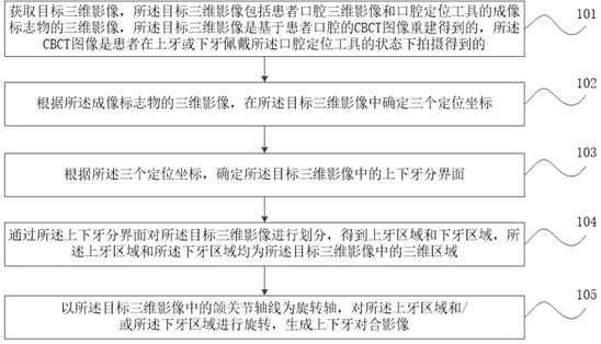
[0093] figure 1 It is a flow chart of the steps of a method for simulating upper and lower teeth alignment provided by the embodiment of the present invention, as shown in figure 1 As shown, the method includes:
[0094] Step 101. Obtain a three-dimensional image of a target, the three-dimensional image of the target includes a three-dimensional image of the patient's oral cavity and a three-dimensional image of an imaging marker of an oral po...
PUM
 Abstract
Description
Claims
Application Information