
Anti-precipitation device for foam extinguishing agent

A foam fire extinguishing agent and anti-precipitation technology, which is applied to mixers with rotating stirring devices, dissolvers, mixers, etc., can solve the problems of poor foam fire extinguishing agent precipitation and achieve the effect of reducing costs

Pending Publication Date: 2021-12-28
江苏优尼科工业消防有限公司
View PDF0 Cites 1 Cited by
  • Summary
  • Abstract
  • Description
  • Claims
  • Application Information

AI Technical Summary

Problems solved by technology

[0003] The object of the present invention is to provide a kind of anti-precipitation device for foam fire extinguishing agent, to solve the problem that the foam fire extinguishing agent precipitation effect is poor in the above-mentioned background technology

Method used


Image

  • Anti-precipitation device for foam extinguishing agent
  • Anti-precipitation device for foam extinguishing agent
  • Anti-precipitation device for foam extinguishing agent

Examples


Embodiment 1

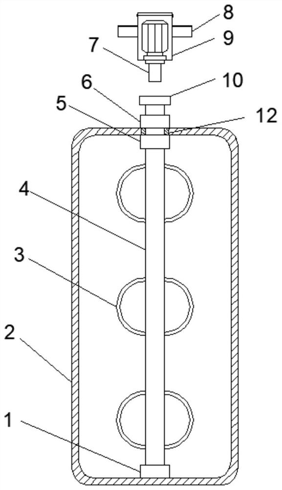
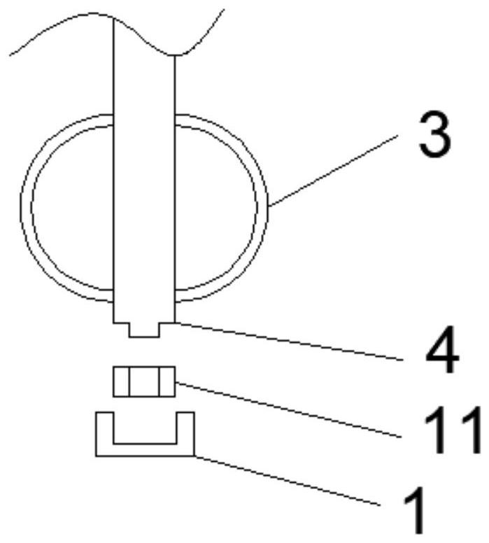
[0018] see Figure 1-4 , the present invention provides a technical solution: an anti-sedimentation device for foam fire extinguishing agent, please refer to figure 1 Specifically, there is a tank body 2, the bottom surface of the tank body 2 is provided with a fixed block 1, and the fixed block 1 is fixedly connected with the tank body 2, the upper end surface of the fixed block 1 is provided with a stirring rod 4, and the stirring rod 4 is movable with the fixed block 1 The connection can support the stirring rod 4 when stirring, and can prevent the rotation of the stirring plate 4 from causing damage to the bottom end surface of the inner cavity of the tank body 2.

[0019] see figure 1 , the outer wall of the stirring rod 4 is provided with six sets of stirring rings 3, and the stirring rings 3 and the stirring rod 4 are detachably connected, and each group of stirring rings 3 is arranged oppositely, and the stirring rings 3 are arranged on the outer wall of the stirring ...

Embodiment 2

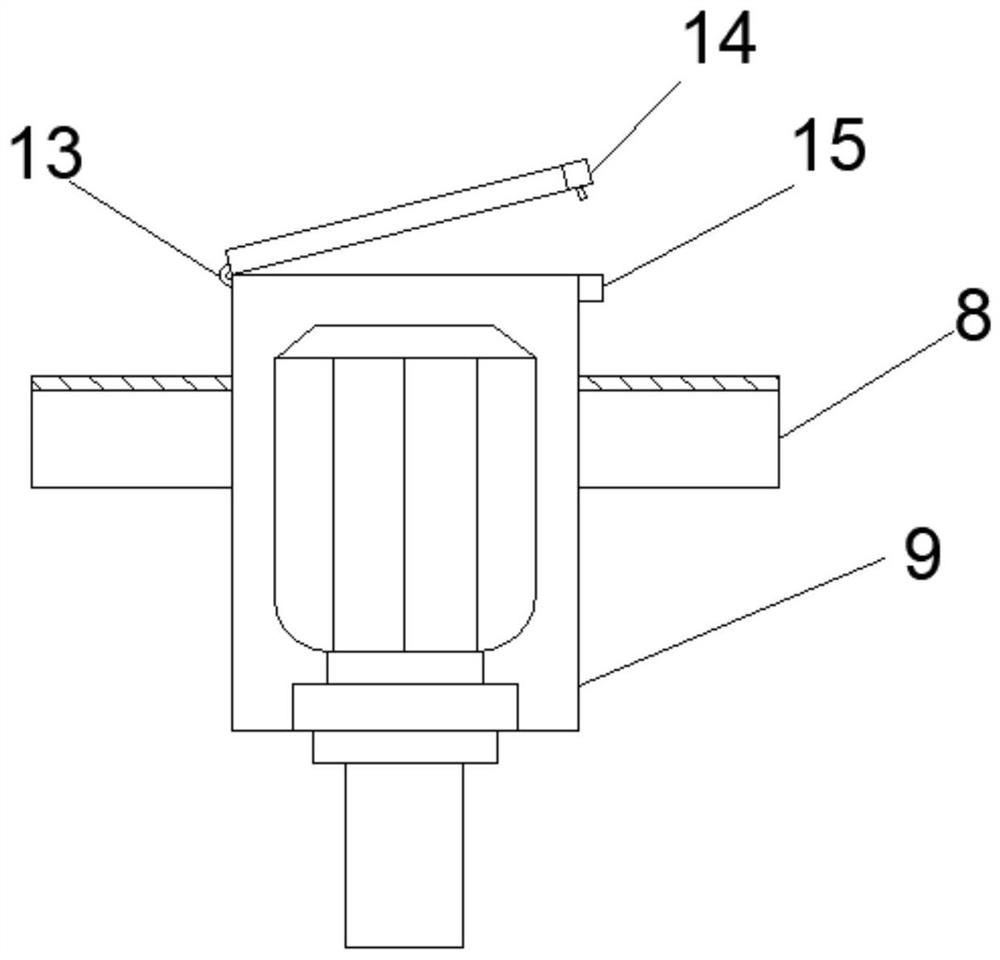
[0026] Such as image 3 As shown, the difference from the previous embodiment is that the top surface of the motor housing 9 is provided with a rectangular opening 2, a maintenance door is provided at the rectangular opening 2, and a movable hinge 13 is provided on the left side of the maintenance door. 13 One end that is not connected with the maintenance door is movably connected with the motor housing 9, the left side of the maintenance door is provided with a buckle 14, and the buckle 14 is detachably connected with the maintenance door, the right side of the motor housing 9 is connected to the The corresponding position of the buckle 14 is provided with a draw-in groove 15 matching the buckle 14, and the draw-in groove 15 is detachably connected with the motor housing 9, which can be more convenient for people's work when repairing and maintaining the motor.

[0027] Such as image 3 As shown, the top surface of the handle 8 at both ends of the motor housing 9 is provide...


PUM


Abstract

The invention discloses an anti-precipitation device for a foam extinguishing agent, and belongs to the technical field of fire fighting equipment. The device specifically comprises a tank body, a fixing block is arranged on the bottom end surface of the tank body; a stirring rod is arranged on the upper end surface of the fixed block; six groups of stirring rings are arranged on the outer wall of the stirring rod; a bearing I is arranged in the center of the top end surface of the inner cavity of the tank body; the inner ring of the bearing I is sleeved on the outer wall of the stirring rod, a bearing II is arranged at the position corresponding to the bearing I, the inner ring of the bearing II is sleeved on the outer wall of the stirring rod, the bearing II is movably connected with the stirring rod, a connecting block is arranged at the top end of the stirring rod, and the top end surface of the connecting block is circular in shape; a connecting rod is arranged at the sunken position of the connecting block, a motor shell is arranged on the top end face of the connecting rod, a motor rotating shaft of a motor in an inner cavity of the motor shell is movably connected with the connecting rod, and handles are arranged on the side faces of the two ends of the motor shell. The invention aims to solve the problem of precipitation of the foam extinguishing agent.

Description

technical field [0001] The invention relates to the technical field of fire fighting equipment, in particular to an anti-precipitation device for foam fire extinguishing agent. Background technique [0002] Foam fire extinguishing agent is an effective fire extinguishing agent for extinguishing flammable and combustible liquids. It mainly generates a condensed foam floating layer on the surface of the liquid to suffocate and cool the fire. Foam fire extinguishing agents are divided into chemical foam, air foam, fluoroprotein foam, water-based Membrane foam and alcohol-resistant foam, etc., have a wide range of applications. Due to the chemical characteristics of the foam fire extinguishing agent itself, when it is stored in the storage tank of a fire truck for a long time, it is easy to precipitate, and the effect of the precipitated foam fire extinguishing agent is poor. The foam is less, which seriously affects the use. Contents of the invention [0003] The purpose of ...

Claims


Application Information

Patent Timeline
IPC IPC(8): B01F7/16B01F15/00
Inventor 姚高坤
Owner 江苏优尼科工业消防有限公司
Learn More