Axle half-shaft structure
A shaft structure and axle technology, applied in axles, wheels, vehicle parts, etc., can solve problems such as unfavorable lightweight requirements, inconvenient installation and disassembly, and poor stability, so as to improve connection stability, reduce weight, and reduce overall weight Effect
- Summary
- Abstract
- Description
- Claims
- Application Information
AI Technical Summary
Problems solved by technology
Method used
Image

Examples
Embodiment 1
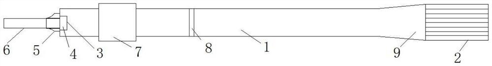
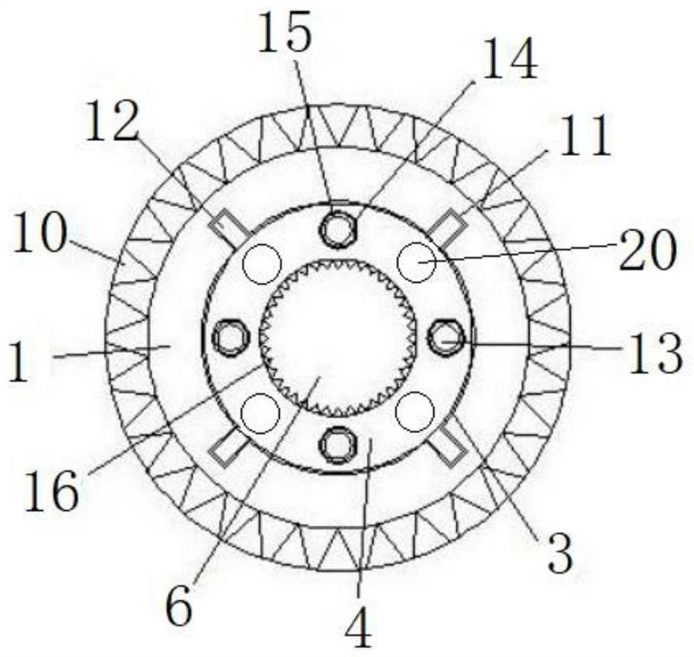
[0034] Such as figure 1 and figure 2 As shown, in this embodiment, the positioning and assembly mechanism includes a locking screw 13, a positioning block 12 located on the outer side wall of the fixed plate 4, a positioning slot 11 located on the side wall of the installation groove 3, and a positioning groove located on the bottom surface of the installation groove 3. The positioning screw hole 15, the fixed plate 4 is provided with a matching positioning hole 14, and the locking screw 13 passes through the matching positioning hole 14 and is locked and connected with the positioning screw hole 15, and the positioning block 12 is snapped into the positioning groove 11 Cooperate. By setting a positioning groove in the mounting groove at one end of the half shaft, and setting a positioning block on the fixed plate to match with the positioning groove for positioning and clamping, it not only realizes the function of pre-positioning, but also has the function of limiting; thr...
Embodiment 2
[0043] The difference between this embodiment and Embodiment 1 is that the connecting end of the spline shaft is arranged in a detachable connection structure, which facilitates the replacement of spline shafts of different specifications and improves practicability. Such as Figure 4 As shown, the spline shaft 2 is connected to one end of the half shaft main body 1 through a flange 17 . Specifically, a plurality of fastening holes can be provided on the circumferential side wall of the flange, and the fastening bolts can pass through the fastening holes to perform fastening installation and connection with the spline shaft. This structural setting facilitates the installation and disassembly of the spline shaft through the flange.
Embodiment 3
[0045] The difference between this embodiment and Embodiment 2 is that the free end of the spline shaft 2 is provided with a center 19 , and the free end of the spline shaft 2 is formed with an annular groove surrounding the center 19 . The center point is set at the free end of the spline shaft, which can contact with the cross shaft in the differential, reducing the wear caused by relative movement.
PUM
 Abstract
Description
Claims
Application Information
 - Generate Ideas
- Intellectual Property
- Life Sciences
- Materials
- Tech Scout
- Unparalleled Data Quality
- Higher Quality Content
- 60% Fewer Hallucinations
Browse by: Latest US Patents, China's latest patents, Technical Efficacy Thesaurus, Application Domain, Technology Topic, Popular Technical Reports.
© 2025 PatSnap. All rights reserved.Legal|Privacy policy|Modern Slavery Act Transparency Statement|Sitemap|About US| Contact US: help@patsnap.com