
Bearing convenient to mount

A bearing and mounting block technology, applied in the direction of bearing components, shafts and bearings, rigid brackets of bearing components, etc., can solve the problems of radial size, large vibration and noise, reduce friction coefficient, difficult bearing maintenance, etc., to improve the connection. speed, improved usability, improved connection reliability

Inactive Publication Date: 2021-12-28
谢彬
View PDF0 Cites 0 Cited by
  • Summary
  • Abstract
  • Description
  • Claims
  • Application Information

AI Technical Summary

Problems solved by technology

[0002] Bearing is an important part of contemporary mechanical equipment. Its main function is to support the mechanical rotating body, reduce the friction coefficient during its movement, and ensure its rotation accuracy. Bearings can be divided into two categories: rolling bearings and sliding bearings. Rolling bearings have been standardized and serialized, but compared with sliding bearings, their radial dimensions, vibration and noise are larger, and their prices are higher
[0003] During the installation process of the bearing assembly, the bearing assembly is usually installed and clamped by clamping, and it is troublesome to install the bearing and the assembly together, wasting a lot of time, and it is inconvenient to disassemble. When the bearing is damaged, it is not necessary It is convenient to disassemble, which makes the maintenance of the bearing more difficult. Now a bearing that is easy to install is proposed to solve the above-mentioned problems

Method used


Image

  • Bearing convenient to mount
  • Bearing convenient to mount
  • Bearing convenient to mount

Examples


Embodiment Construction

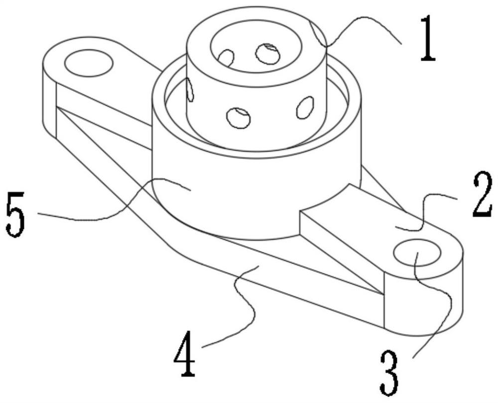
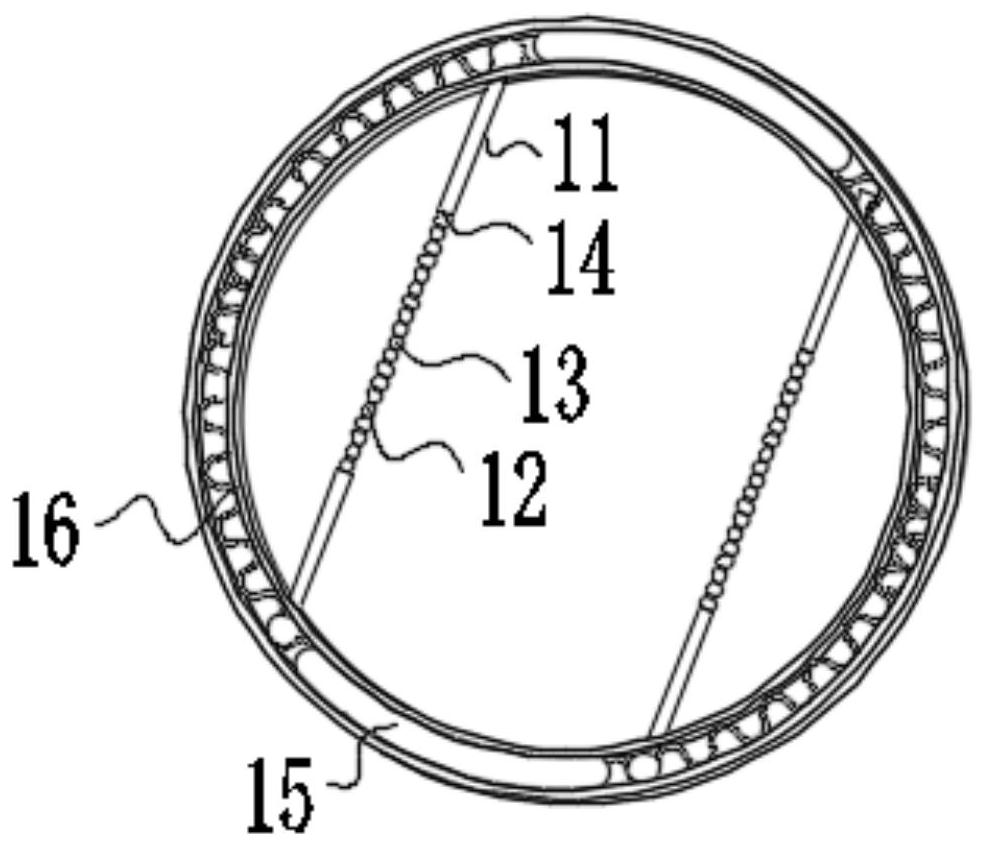
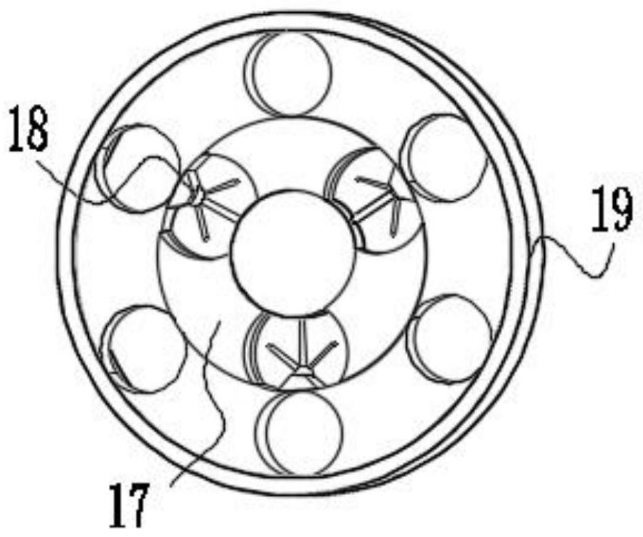
[0024] use Figure 1-Figure 7 An easy-to-mount bearing according to an embodiment of the present invention will be described as follows.

[0025] Such as Figure 1-Figure 7 As shown, an easy-to-install bearing of the present invention includes a connecting sleeve 1; The two ends of the mounting block 2 are symmetrically arranged, and the right end of the fixing column 5 is fixedly connected with the left end of the mounting block 2, the axis of the mounting block 2 is provided with a mounting hole 3, and the bottom of the fixing column 5 is provided with a bottom plate 4, and fixed The bottom of the column 5 is fixedly connected with the top of the bottom plate 4, and the purpose of setting the fixed column 5 is to improve the stability of the bearing.

[0026] The top of the connecting sleeve 1 is provided with a contraction ring 15, and the interior of the contraction ring 15 is symmetrically provided with a contraction spring 16, and the inner wall of the contraction ring...


PUM


Abstract

The invention belongs to the field of bearings, and particularly relates to a bearing convenient to mount. The bearing comprises a connecting sleeve; a fixing column is arranged at the bottom of the connecting sleeve; the bottom of the connecting sleeve is fixedly connected with the top of the fixing column; mounting blocks are symmetrically arranged at the two ends of the fixing column; the right end of the fixing column is fixedly connected with the left ends of the mounting blocks; mounting holes are formed in the axis centers of the mounting blocks; a bottom plate is arranged at the bottom of the fixing column; the bottom of the fixing column is fixedly connected with the top of the bottom plate; a contraction ring is arranged at the top of the connecting sleeve; contraction springs are symmetrically arranged in the contraction ring; the inner wall of the contraction ring is contact with the outer surfaces of the contraction springs; limiting rods are symmetrically arranged at both ends of the contraction springs; the top ends of the contraction springs are fixedly connected with the tops of the limiting rods; contraction mechanisms are arranged at the bottoms of the limiting rods; the bottom of the limiting rods are fixedly connected with the tops of the contraction mechanisms; and contraction rods are arranged at the bottoms of the contraction mechanisms.

Description

technical field [0001] The invention belongs to the field of bearings, in particular to an easy-to-install bearing. Background technique [0002] Bearing is an important part of contemporary mechanical equipment. Its main function is to support the mechanical rotating body, reduce the friction coefficient during its movement, and ensure its rotation accuracy. Bearings can be divided into two categories: rolling bearings and sliding bearings. Rolling bearings have been standardized and serialized, but compared with sliding bearings, their radial dimensions, vibration and noise are larger, and their prices are also higher. [0003] During the installation process of the bearing assembly, the bearing assembly is usually installed and clamped by clamping, and it is troublesome to install the bearing and the assembly together, wasting a lot of time, and it is inconvenient to disassemble. When the bearing is damaged, it is not necessary It is convenient to disassemble, which make...

Claims


Application Information

Patent Timeline
Patent Type & Authority Applications(China)
IPC IPC(8): F16C35/00
CPCF16C35/00
Inventor 谢彬
Owner 谢彬
Learn More