
I/F circuit linearity calibration method and system

A calibration method and a calibration system technology, applied in the direction of electronic circuit testing, measuring electricity, measuring electrical variables, etc., can solve problems such as influence, achieve the effect of reducing test error and improving test accuracy

Active Publication Date: 2021-12-28
HUNAN AEROSPACE ELECTROMECHANICAL EQUIP & SPECIAL MATERIAL INST
View PDF3 Cites 0 Cited by
  • Summary
  • Abstract
  • Description
  • Claims
  • Application Information

AI Technical Summary

Problems solved by technology

[0005] The problem to be solved by the present invention is to provide an I / F circuit linearity calibration method and system for the problem that the output current linearity of the constant current source in the prior art affects the I / F circuit linearity test results

Method used


Image

  • I/F circuit linearity calibration method and system
  • I/F circuit linearity calibration method and system
  • I/F circuit linearity calibration method and system

Examples


Embodiment 1

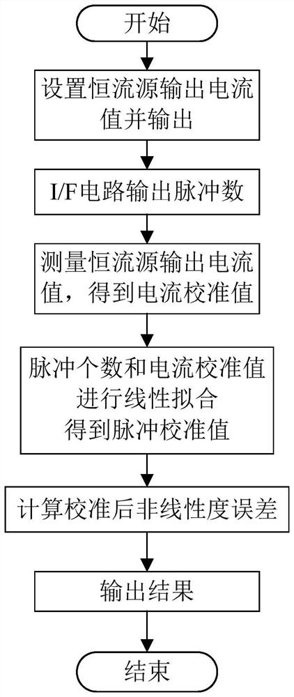
[0040] Such as figure 1 As shown, the present invention provides a kind of I / F circuit linearity calibration method, and described I / F circuit linearity calibration method comprises the steps:

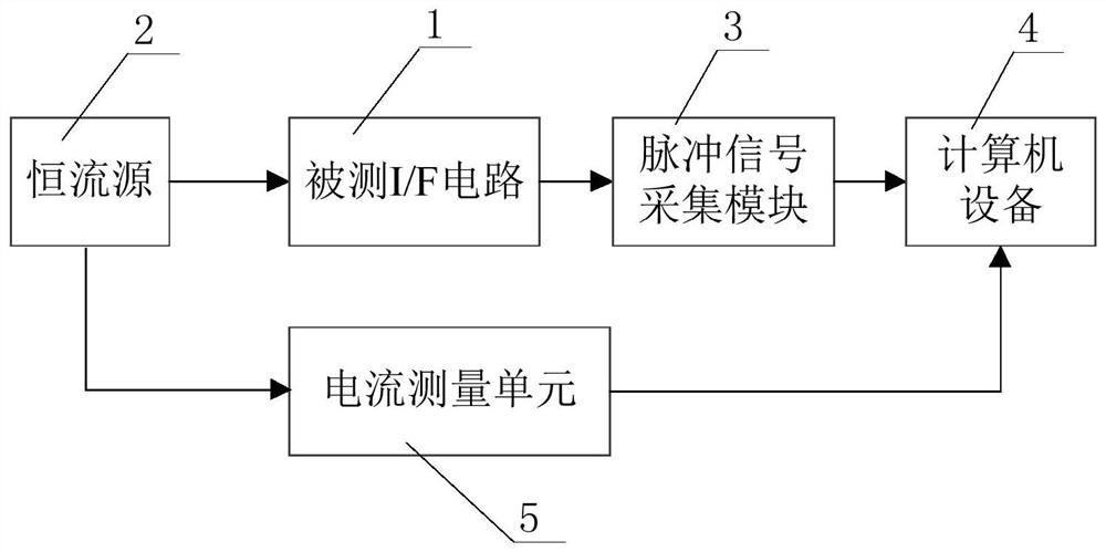
[0041] Step (A): The constant current source 2 outputs the i-th current value A i As the i-th input value of the tested I / F circuit 1, i=1,2,...,N, N≥6, A 1 、A 2 ,...,A N For different current values, the i-th pulse measurement value F is obtained according to the i-th output value of the I / F circuit 1 i , the pulse measurement value is the number of pulses output by the tested I / F circuit 1 per second.

[0042] In a preferred implementation manner, the pulse measurement value can be obtained by averaging the number of pulses output by the I / F circuit in L seconds, L≥5. L can be 30 in this embodiment. That is, the collection current point A i The number of 30-second pulses output by the corresponding I / F circuit, and then divided by 30, is the number of pulses per second, which ...

Embodiment 2

[0074] The difference between this embodiment 2 and embodiment 1 is that the step (B) is replaced by the following step (B1):

[0075] Step (B1): Determine whether the constant current source 2 used in the last execution of the I / F circuit linearity calibration method is the same as the constant current source 2 used in the execution of the I / F circuit linearity calibration method this time, and determine whether the last execution of the I / F circuit linearity calibration method is the same. Whether to obtain the i-th current value A during the linearity calibration method of the F circuit i Corresponding i-th current calibration value A' i , and judge whether the time interval between executing the I / F circuit linearity calibration method last time and this execution I / F circuit linearity calibration method is not greater than the preset time interval, if the judgment results are all yes, then adopt the last execution I The current calibration value A' obtained in the / F cir...


PUM


Abstract

The invention provides an I / F circuit linearity calibration method and system. The I / F circuit linearity calibration method comprises the steps that (A) a constant current source outputs an ith current value as an ith input value of a measured I / F circuit, an ith pulse measurement value is obtained according to an ith output value of the I / F circuit, and the pulse measurement value is the number of pulses output by the measured I / F circuit per second; (B) the ith current value Ai output by the constant current source is collected by a current measurement unit, the obtained measurement result of the current measurement unit is the ith current calibration value, and the measurement precision of the current measurement unit is higher than the output current precision of the constant current source; (C) the current calibration values serve as x coordinates, the pulse measurement values serve as y coordinates, linear fitting is conducted on the N current calibration values and the N pulse measurement values, the slope and the intercept of a fitting straight line are obtained, and the ith pulse calibration value is obtained; and (D) the calibrated nonlinearity error of the measured I / F circuit is calculated according to the N value, the N pulse measurement values and the N pulse calibration values.

Description

technical field [0001] The invention relates to a method and system for calibrating the linearity of an I / F circuit, belonging to the field of I / F circuit testing of an accelerometer in an inertial navigation system. Background technique [0002] The linearity of the I / F circuit in the accelerometer is one of the important factors affecting the dynamic performance of inertial navigation products. At present, the linearity test of the I / F circuit of inertial navigation products is mostly based on the constant current provided by the multi-function calibrator or the source device (that is, the constant current source). [0003] At present, there are very few units in the world that produce multi-power calibrator or source (current) equipment, and there is no linearity index requirement in related equipment. Only a few models of high-precision multi-function calibrator can meet the linearity index requirement of high-precision I / F circuit. , but this equipment is imported equi...

Claims


Application Information

Patent Timeline
IPC IPC(8): G01R31/28G01C25/00
CPCG01R31/282G01C25/005
Inventor 彭时雨陈晖黎正华陈奕贝郑巍刘晓梅杨淇
Owner HUNAN AEROSPACE ELECTROMECHANICAL EQUIP & SPECIAL MATERIAL INST
Learn More