Electromagnetic switch device with adjustable force

An electromagnetic switch and force adjustment technology, applied in electric switches, power devices inside switches, electromagnetic relays, etc., can solve the problems of reduced service life, contact wear, poor experience, etc., and achieve the effect of prolonging service life

Pending Publication Date: 2021-12-28
加百裕(南通)电子有限公司
View PDF0 Cites 0 Cited by
  • Summary
  • Abstract
  • Description
  • Claims
  • Application Information

AI Technical Summary

Problems solved by technology

[0003] The magnetic force generated by the electromagnetic component of the existing electromagnetic switch is fixed, and the switching force is fixed, but the force may not be suitable for different users, and different users may experience poor experience. At the same time, because the moment the electromagnetic component is connected, the magnetic force suddenly acts on the two contacts As time goes by, multiple rapid collisions of the two contacts will lead to serious wear of the contacts and reduce the service life. Therefore, in order to solve the above problems, an electromagnetic switch device with adjustable force is proposed

Method used


Image

  • Electromagnetic switch device with adjustable force
  • Electromagnetic switch device with adjustable force
  • Electromagnetic switch device with adjustable force

Examples


Embodiment 1

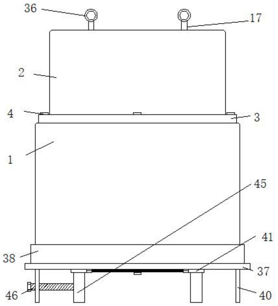
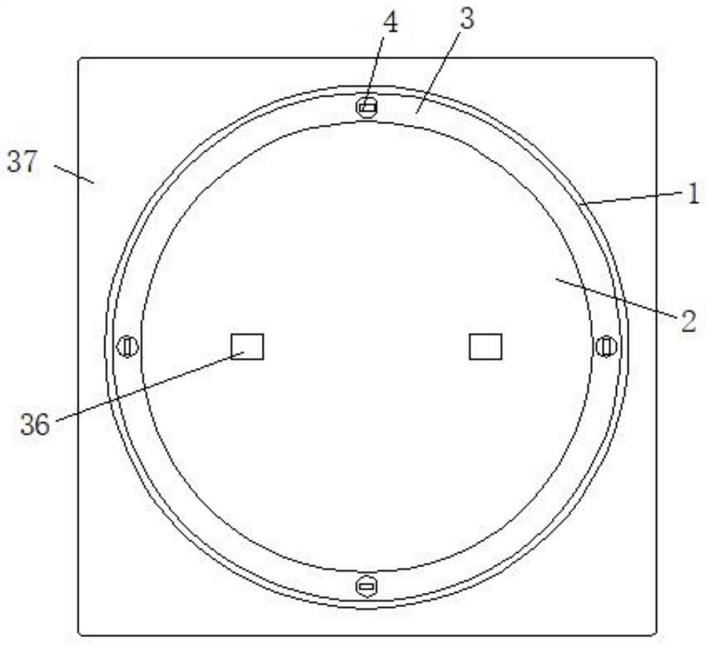
[0029] Embodiment one, such as Figure 1-7As shown, an electromagnetic switch device with adjustable force includes a first housing 1, a second housing 2 is arranged above the first housing 1, and both the first housing 1 and the second housing 2 are in a cylindrical shape. , the outer diameter of the first housing 1 is greater than the outer diameter of the second housing 2, the outer wall of the second housing 2 is fixedly connected with a connecting ring 3, the connecting ring 3 is welded to the second housing 2, and the connecting ring 3 is connected by a plurality of connecting screws 4. It is fixedly connected with the upper wall of the first shell 1. The bottom surface of the first shell 1 is threadedly connected with the installation cylinder 5. The bottom surface of the installation cylinder 5 is provided with a concave groove, which is convenient for rotating installation. The upper surface of the installation cylinder 5 is fixedly connected with the installation ring...

Embodiment 2

[0030] Embodiment two, such as Figure 4 , 7 As shown, the outer sides of the two first contacts 13 are horizontally provided with installation grooves 23, and the two installation grooves 23 are fixedly connected with the inner wall of the second housing 2. The two installation grooves 23 are arranged symmetrically, and the installation grooves 23 Located between the first contact 13 and the second contact 16, a groove 24 is horizontally arranged on the side of the installation groove 23 facing the fixed iron core 7, and a vertically arranged moving piece 25 is slidably connected in the groove 24 to move The sheet 25 is fixedly connected to the inner wall of the groove 24 through the extrusion spring 26, and the side of the moving sheet 25 facing the fixed iron core 7 is fixedly connected with a deceleration rod 27 arranged horizontally, and the end of the deceleration rod 27 away from the moving sheet 25 is fixedly connected with a deceleration block 28. The deceleration bl...

Embodiment 3

[0031] Embodiment three, such as Figure 4 , 6 As shown, a stabilizing ring 30 is provided above the two second contacts 16, and the two stabilizing rings 30 are respectively sleeved on the corresponding movable rods 17 and slidably connected thereto. The rod 31 is fixedly connected to the inner wall of the second housing 2, and the two stabilizing rings 30 are fixedly connected through two arc-shaped linkage rods 32. The stabilizing ring 30 is used to limit the movable rod 17 and determine the moving direction of the movable rod 17. The moving rod 17 can only move up and down, so as to ensure the accurate docking of the second contact 16 and the first contact 13 .


PUM


Abstract

The invention discloses an electromagnetic switch device with an adjustable force, and the switch device comprises a first shell; a second shell is arranged above the first shell, the first shell and the second shell are both cylindrical, the outer diameter of the first shell is greater than the outer diameter of the second shell, the outer wall of the second shell is fixedly connected with a connecting ring, the connecting ring is fixedly connected with the upper wall of the first shell through a plurality of connecting screws, the bottom surface of the first shell is in threaded connection with a mounting cylinder, the upper surface of the mounting cylinder is fixedly connected with a mounting ring, a fixed iron core is vertically arranged above the mounting cylinder, and the fixed iron core is in threaded connection with the mounting ring. By arranging the fixed iron core for adjusting the position and adjusting the relative position of the fixed iron core and the coil, the magnetic force is adjusted to be suitable for different users, meanwhile, the deceleration block is arranged to intercept the movement of the second contact, so that the contact between the second contact and the first contact is gentle, the device assembly is protected, the service life of the device assembly is prolonged, and the practicability is high.

Description

technical field [0001] The invention relates to the technical field of electromagnetic switches, in particular to an electromagnetic switch device with adjustable force. Background technique [0002] Electromagnetic switch, as the name implies, is a switch controlled by an electromagnet, that is, a combination of an electromagnet and a switch. When the electromagnet coil is energized, electromagnetic attraction is generated, and the movable iron core pushes or pulls the switch contacts to close, thereby connecting the controlled circuit. [0003] The magnetic force generated by the electromagnetic component of the existing electromagnetic switch is fixed, and the switching force is fixed, but the force may not be suitable for different users, and different users may experience poor experience. At the same time, because the moment the electromagnetic component is connected, the magnetic force suddenly acts on the two contacts As time goes by, multiple rapid collisions of the...

Claims


Application Information

Patent Timeline
IPC IPC(8): H01H3/28H01H9/02H01H1/14H01H50/44H01H50/36H01H50/54H01H50/30H01H50/02
CPCH01H3/28H01H9/02H01H1/14H01H50/44H01H50/36H01H50/54H01H50/30H01H50/02
Inventor 孙子惠
Owner 加百裕(南通)电子有限公司
Why Eureka
Try Eureka