Unlock instant, AI-driven research and patent intelligence for your innovation.

Sand mould identification device

A technology for identifying devices and sand molds, which is applied to casting molding equipment, metal processing equipment, manufacturing tools, etc., and can solve problems such as the difficulty of reducing quality costs

Pending Publication Date: 2021-12-28
DISA IND
View PDF4 Cites 0 Cited by
  • Summary
  • Abstract
  • Description
  • Claims
  • Application Information

AI Technical Summary

Problems solved by technology

Therefore, further reducing the cost of quality has proven to be very difficult

Method used


Image

  • Sand mould identification device
  • Sand mould identification device
  • Sand mould identification device

Examples


Embodiment Construction

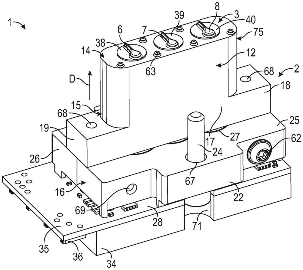
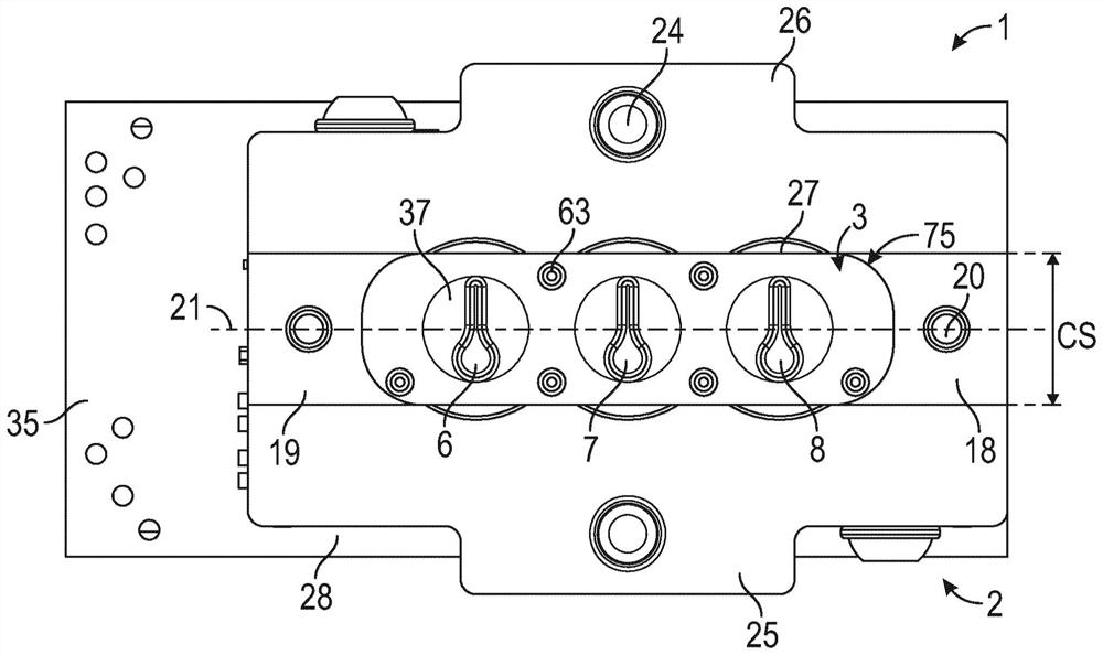
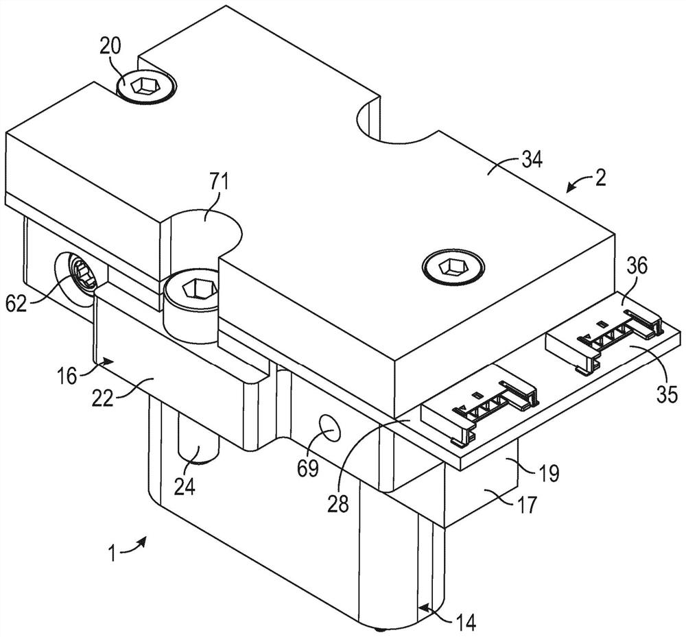
[0043] figure 1 Shown is a sand mold identification device 1 having a housing 2 comprising a Figure 10 to Figure 15 The identification pattern surface 3 in the pattern forming surface 4 of the sand mold molding machine 5 is shown. Alternatively, the identification pattern surface 3 can be arranged in a pattern forming surface of a core shooter, not shown. The identification pattern face 3 is suitable for printing or embossing an individual identification pattern in a sand mold or a core for a sand mold. The individual identification pattern can then be reproduced in the metal casting. Three individually adjustable indicator elements 6, 7, 8 are rotatably arranged in the identification pattern surface 3, and the rotational position of each individual indicator element 6, 7, 8 can be controlled by the actuator 9, 10, 11 adjustment, such as Figure 5 , Figure 6 and Figure 7 shown. The housing 2 includes an insertion portion 12 adapted to be inserted into a Figure 10 I...


PUM


Abstract

The sand mould identification device (1) has a housing (2) with an identification pattern face (3) adapted to be arranged in a pattern forming surface (4) of a sand moulding machine. Individually adjustable indicator elements (6, 7, 8) in the identification pattern face are adjustable by means of an actuators (9, 10, 11). The housing includes an insertion portion (12) adapted to be inserted into a corresponding recess of said sand moulding machine. The identification pattern face is located at a front end (14) of the insertion portion. The insertion portion is adapted to be inserted into the sand moulding machine in an insertion direction (D) extending from a rear end (15) to the front end (14) of the insertion portion. A mounting bracket is accessible at or behind the rear end (15) of the insertion portion for mounting or demounting the housing to or from the sand moulding machine or core shooter.

Description

technical field [0001] The invention relates to a sand mold identification device having a housing comprising an identification pattern surface adapted to be arranged in the pattern forming surface of a sand mold molding machine or a core shooting machine, wherein a plurality of individually adjustable indicator elements are rotatable Arranged in the face of the identification pattern, the rotational position of each individual indicator element can be adjusted by an actuator, wherein the housing includes an insertion part suitable for being inserted into the sand molding machine or core shooting machine corresponding recesses and having front and rear ends, wherein the identification pattern face is located at the front end of an insertion portion, wherein at least a portion of each actuator is inserted into the insertion portion, and wherein the housing includes a Machine or core shooter installation device. Background technique [0002] WO 2017 / 025266 A1 discloses a sand...

Claims


Application Information

Patent Timeline
IPC IPC(8): B22C7/00B22C7/04B22C23/00B29C33/42
CPCB22C7/005B22C7/04B22C23/00
Inventor P·拉森H·韦格
Owner DISA IND