Gel pen plastic tube refill with metal head convenient to replace and install
A gel pen and plastic tube technology, which is applied to devices for removing the pen tip, printing, writing utensils, etc., can solve the problems of falling off, the pen tip of the gel pen is small, and it is not easy to snap together.
- Summary
- Abstract
- Description
- Claims
- Application Information
AI Technical Summary
Problems solved by technology
Method used
Image
Examples
Embodiment 1
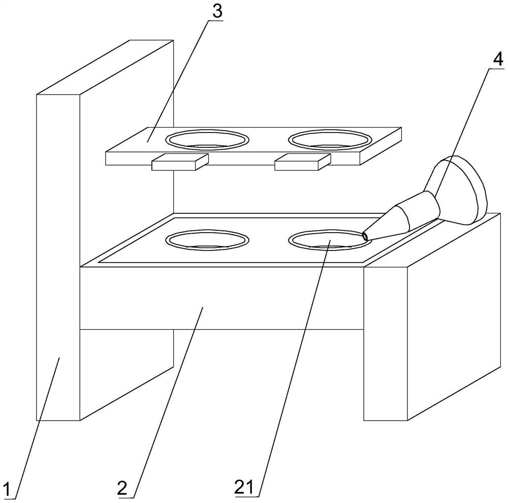
[0035] Such as Figure 1-6 As shown, the present invention provides a gel pen plastic tube refill that is easy to replace and install a metal tip, including a workbench 1, a metal nib clip connector 2, a refill fixing device 3 and a water inlet nib clip replacement device 4, The top outer surface of the workbench 1 is provided with a metal nib snap connector 2, the right outer surface of the workbench 1 is provided with a pen core fixing device 3, and the top right outer surface of the workbench 1 is movably lapped with a water inlet The nib snaps into the changer 4.
[0036] In this embodiment, the pen tube is put through the pen core fixing device 3 into the inside of the metal nib clip adapter 2, and one end of the nib is pressed by the water-inlet nib clip replacement device 4 to clip the nib, Or use the water-inlet nib snap-in changer 4 to replace the nib of the pen core.
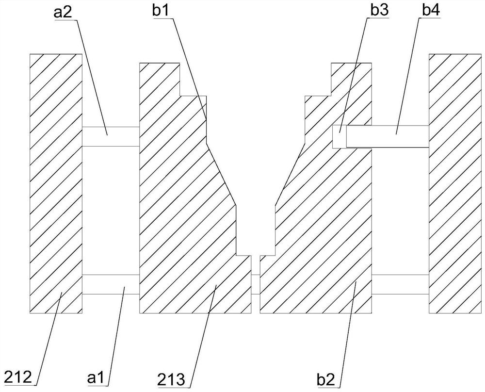
[0037] Such as Figure 1-6As shown, in this embodiment, preferably, a sliding bar a1 is fixedly ...
Embodiment 2
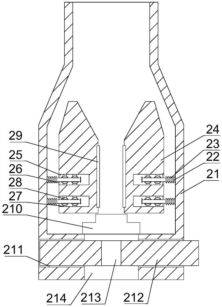
[0039] Such as Figure 1-6 As shown, on the basis of Embodiment 1, the present invention provides a technical solution: preferably, a nib snap joint 21 is provided on the outer surface of the metal nib snap connector 2, and on the inner surfaces of the left and right sides of the nib snap joint 21 Fixedly connected with a fixed post-22, the outer surface of the fixed post-22 is movably sleeved with an elastic wire 23; Square empty slot 25, the outlet of square empty slot 25 is fixedly connected with spring extruding block 26 on the upper and lower outer surfaces, and is fixedly connected with fixed column two 27 on the upper and lower inner surfaces of square empty slot 25, and is fixed on one end of fixed column two 27 Connected with a circular limiting block 28, the outer surface of the circular limiting block 28 is movably socketed on the outer surface of the fixed column 1 22, and a friction panel 29 is fixedly connected to the outer surface of one side of the extruding bl...
Embodiment 3
[0042] Such as Figure 1-6 As shown, on the basis of Embodiment 1, the present invention provides a technical solution: preferably, one end of the refill fixing device 3 is provided with an arc-shaped block 31, and one end on the left side of the arc-shaped block 31 is fixedly connected with a fixed block, the outer surface of the fixed block is fixedly connected with an arc-shaped fitting panel 32, and there are two arc-shaped fitting panels 32, and one end of the other end arc-shaped block 31 is fixedly connected with a square casing 33, and the arc-shaped fitting panel 32 is fixedly connected with a square casing 33. The outer surface of one side of the joint panel 32 is provided with a friction soft rubber layer, and the inside of the square casing 33 is movably connected with a pressing block 34, and one end of the pressing block 34 is fixedly connected to the outer surface of one side of the arc-shaped joint panel 32. .
[0043] In this embodiment, the pen tube passes t...
PUM
 Abstract
Description
Claims
Application Information
 - R&D
- Intellectual Property
- Life Sciences
- Materials
- Tech Scout
- Unparalleled Data Quality
- Higher Quality Content
- 60% Fewer Hallucinations
Browse by: Latest US Patents, China's latest patents, Technical Efficacy Thesaurus, Application Domain, Technology Topic, Popular Technical Reports.
© 2025 PatSnap. All rights reserved.Legal|Privacy policy|Modern Slavery Act Transparency Statement|Sitemap|About US| Contact US: help@patsnap.com


