
Special transportation device for transformer and special distribution transformer

A technology for distribution transformers and transportation devices, applied in the field of transformers, can solve the problems of transformer bump damage, no shock absorption, protective measures, and loose internal electrical components, so as to prevent shaking and falling off, improve protection effect, and enhance protection effect Effect

Inactive Publication Date: 2021-12-31
魏朝辉
View PDF0 Cites 2 Cited by
  • Summary
  • Abstract
  • Description
  • Claims
  • Application Information

AI Technical Summary

Problems solved by technology

[0004] The purpose of the present invention is to solve the problem that there are no corresponding shock absorption and protective measures during the transportation of the transformer. The bumps during the transportation will cause the collision of the transformer, resulting in damage to the external bump of the transformer, and in severe cases, the internal electrical components will be loose or damage problem

Method used


Image

  • Special transportation device for transformer and special distribution transformer
  • Special transportation device for transformer and special distribution transformer
  • Special transportation device for transformer and special distribution transformer

Examples


Embodiment 1

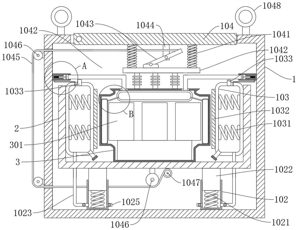
[0031] refer to Figure 1-7 , a special transport device for transformers and a special distribution transformer, including transformer equipment 3, a main box body 1, and also includes: a sleeve 102 fixedly connected in the main box body 1; a fixed column 1022 slidingly connected by a first spring 1021 In the sleeve 102; the connecting pipe 1023 and the air intake pipe 1025 are respectively fixedly connected to one side of the bottom of the sleeve 102; the bottom of the placement box 2 is fixedly connected to the fixed column 1022, wherein the transformer device 3 is placed on the placement box 2; The wrapped airbag 103 is fixedly connected to the inner wall of the placement box 2, wherein the other end of the connecting pipe 1023 leads into the wrapped airbag 103;

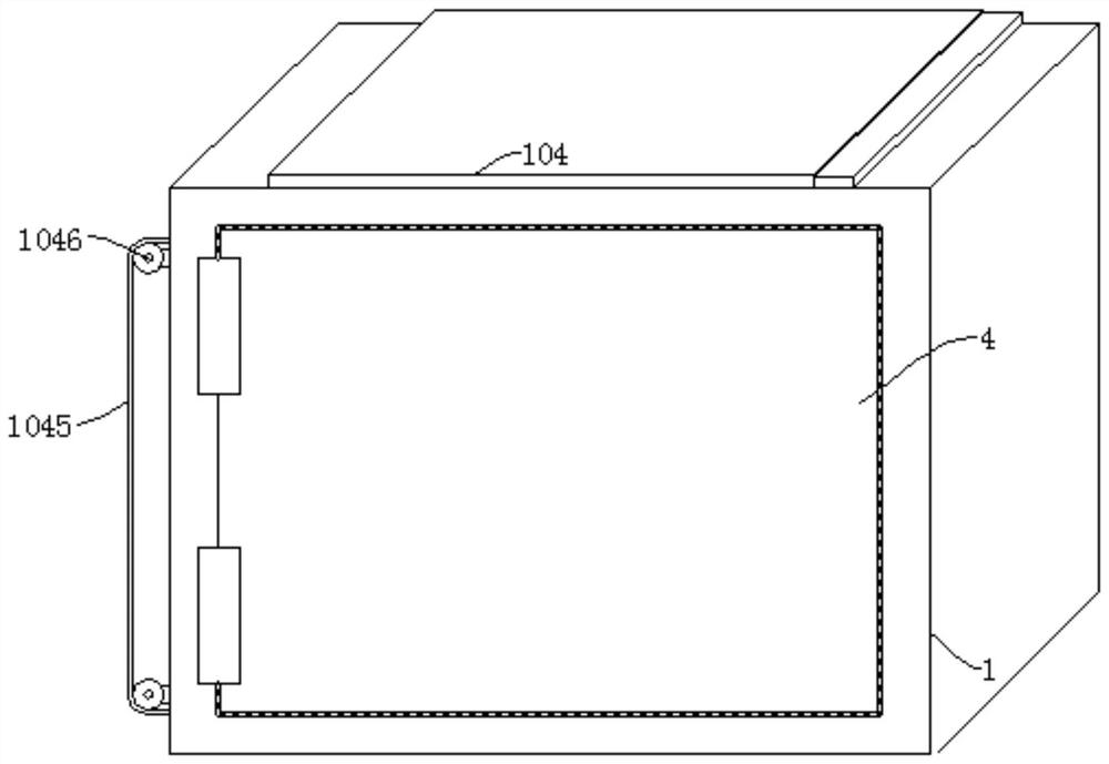
[0032] The main box body 1 is fixed on the compartment by rope binding, and a box door 4 is connected to the side of the main box body 1 by rotation. By opening the box door 4, the transformer equipment 3 is plac...

Embodiment 2

[0034] refer to figure 1 , a special transport device for transformers and a special distribution transformer, including transformer equipment 3, a main box body 1, and also includes: a sleeve 102 fixedly connected in the main box body 1; a fixed column 1022 slidingly connected by a first spring 1021 In the sleeve 102; the connecting pipe 1023 and the air intake pipe 1025 are respectively fixedly connected to one side of the bottom of the sleeve 102; the bottom of the placement box 2 is fixedly connected to the fixed column 1022, wherein the transformer device 3 is placed on the placement box 2; The wrapped airbag 103 is fixedly connected to the inner wall of the placement box 2, wherein the other end of the connecting pipe 1023 leads into the wrapped airbag 103;

[0035] Furthermore, a second spring 1031 is fixedly connected inside the wrapped airbag 103;

[0036] The transformer device 3 is clamped by wrapping the airbag 103 inflated, so that the second spring 1031 is attache...

Embodiment 3

[0038] refer to figure 1 , a special transport device for transformers and a special distribution transformer, including transformer equipment 3, a main box body 1, and also includes: a sleeve 102 fixedly connected in the main box body 1; a fixed column 1022 slidingly connected by a first spring 1021 In the sleeve 102; the connecting pipe 1023 and the air intake pipe 1025 are respectively fixedly connected to one side of the bottom of the sleeve 102; the bottom of the placement box 2 is fixedly connected to the fixed column 1022, wherein the transformer device 3 is placed on the placement box 2; The wrapped airbag 103 is fixedly connected to the inner wall of the placement box 2, wherein the other end of the connecting pipe 1023 leads into the wrapped airbag 103;

[0039] Furthermore, a second spring 1031 is fixedly connected inside the wrapped airbag 103;

[0040] The transformer device 3 is clamped by wrapping the airbag 103 inflated, so that the second spring 1031 is attac...


PUM


Abstract

The invention discloses a special transportation device for a transformer and a special distribution transformer, and belongs to the technical field of transformers. The special transportation device for the transformer comprises transformer equipment, a main box body, a sleeve, a fixed column, a connecting pipe, an air inlet pipe and a placing box, and the sleeve is fixedly connected in the main box body; the fixed column is slidably connected in the sleeve through a first spring; the connecting pipe and the air inlet pipe are fixedly connected to one side of the bottom of the sleeve correspondingly; and the bottom of the placing box is fixedly connected to the fixed column. The transformer equipment is placed in the placing box, damping is provided for the transformer equipment through the first spring, buffering is provided while the transformer equipment is protected through a wrapping air bag, then when the placing box jolts and moves downwards, a traction rope is driven to drive a fixing plate to be tightly attached to the transformer equipment, further protection, damping and buffering effects are provided for the transformer equipment, and the transformer equipment is effectively prevented from being collided and damaged and internal electrical elements are effectively prevented from being loosened and damaged.

Description

technical field [0001] The invention relates to the technical field of transformers, in particular to a special transport device for transformers and a special distribution transformer. Background technique [0002] Transformer refers to a device that uses the principle of electromagnetic induction to change AC voltage, and its main components are primary coil, secondary coil and iron core. [0003] Before installation, the transformer needs to be loaded and transported to the area to be installed. When loading and transporting, the existing box is custom-made through a wooden box, the transformer is placed in the box, and it is directly tied in the compartment with a rope, but both Without corresponding shock absorption and protection measures, the bumps during transportation will cause the transformer to collide, cause the external bump of the transformer to be damaged, and seriously cause the internal electrical components to loosen or be damaged. Contents of the invent...

Claims


Application Information

Patent Timeline
Patent Type & Authority Applications(China)
IPC IPC(8): B65D81/03B65D81/07B65D25/02B65D85/68H01F27/00H01F27/06
CPCB65D81/03B65D81/07B65D25/02B65D85/68H01F27/002H01F27/06
Inventor 魏朝辉
Owner 魏朝辉
Learn More