
Reservoir gate sludge removing device

A technology of removal device and gate, which is applied in hydroelectric power generation, water conservancy projects, cleaning methods and appliances, etc., can solve the problems of poor mud removal effect, impact on drainage, danger, etc., and achieve the effect of improving the removal effect

Active Publication Date: 2021-12-31
广州市庆和源建设有限公司
View PDF4 Cites 1 Cited by
  • Summary
  • Abstract
  • Description
  • Claims
  • Application Information

AI Technical Summary

Problems solved by technology

[0002] Sluices are low-head hydraulic structures built on the banks of rivers, channels, reservoirs, and lakes. Need; open the gate, you can discharge flood, drain water, wash sand, take water or adjust the flow according to the needs of downstream water. The gate is a waterproof tool with a door to prevent and block water. It is usually made of concrete as a wall stack, and other parts are Steel is used for processing, and generally rectangular, circular, or semicircular are used as door leaves. Usually, there will be a lot of silt on the surface of the reservoir gate. If it is not cleaned up in time, it will not only affect the drainage, but also cause certain dangers. Therefore, The sludge on the surface of the gate needs to be treated by a removal device
[0003] When removing the silt on the surface of the gate, part of the silt will dry up on the surface of the gate, resulting in a strong degree of firmness of the silt, but the existing device cannot quickly and effectively process the dried silt, resulting in the silt Poor cleaning effect

Method used


Image

  • Reservoir gate sludge removing device
  • Reservoir gate sludge removing device
  • Reservoir gate sludge removing device

Examples


Embodiment Construction

[0024] Embodiments of the present patent are described in detail below, examples of which are shown in the drawings, wherein the same or similar reference numerals designate the same or similar elements or elements having the same or similar functions throughout. The embodiments described below by referring to the figures are exemplary and are only used for explaining the patent, and should not be construed as limiting the patent.

[0025] In the description of this patent, it is to be understood that the terms "center", "upper", "lower", "front", "rear", "left", "right", "vertical", "horizontal", The orientation or positional relationship indicated by "top", "bottom", "inner", "outer", etc. is based on the orientation or positional relationship shown in the drawings, and is only for the convenience of describing this patent and simplifying the description, rather than indicating or implying References to devices or elements must have a particular orientation, be constructed, ...


PUM


Abstract

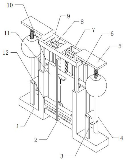
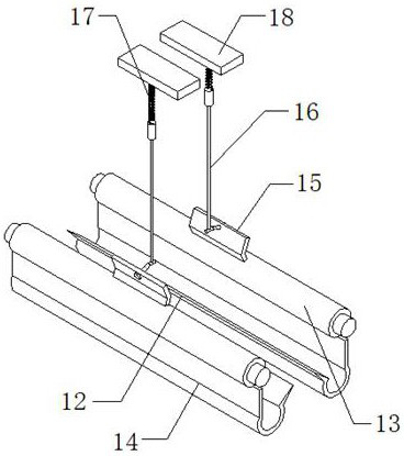
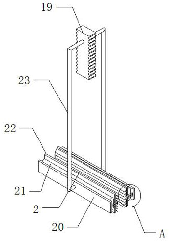
The invention discloses a reservoir gate sludge removing device. The reservoir gate sludge removing device comprises two wall piers and a gate, fixing plates are fixedly connected to the outer walls of the tops of the two wall piers, two storage openings are formed in the two sides of the outer walls of the tops of the fixing plates, winding rollers are rotationally connected to the inner walls of the two storage openings, and inhaul cables are wound on the outer walls of the winding rollers. An inhaul cable is connected with the gate through a bolt, a motor is fixedly connected with the outer wall of one side of a winding roller, the motor is connected with a fixing plate through the bolt, a scraping mechanism is arranged on the outer wall of one side of the gate, and the scraping mechanism comprises a rotating roller, blades and a scraping plate. According to the reservoir gate sludge removing device, stubborn sludge can be cleaned, so that the sludge cleaning effect of the scraping plate is improved, the situation that the sludge cleaning effect is poor due to the fact that the firmness of dried sludge is high is prevented, the sludge cleaning effect is improved conveniently, and the situation that the reservoir gate sludge removing device topples over due to the fact that the stability of the reservoir gate sludge removing device is poor due to rising of the gate is prevented.

Description

technical field [0001] The invention relates to the technical field of water conservancy engineering, in particular to a sludge removal device for a reservoir gate. Background technique [0002] Sluices are low-head hydraulic structures built on the banks of rivers, channels, reservoirs, and lakes. Need; open the gate, you can discharge flood, drain water, wash sand, take water or adjust the flow according to the needs of downstream water. The gate is a waterproof tool with a door to prevent and block water. It is usually made of concrete as a wall stack, and other parts are Steel is used for processing, and generally rectangular, circular, or semicircular are used as door leaves. Usually, there will be a lot of silt on the surface of the reservoir gate. If it is not cleaned up in time, it will not only affect the drainage, but also cause certain dangers. Therefore, The sludge on the surface of the gate needs to be treated by a removal device. [0003] When removing the si...

Claims


Application Information

Patent Timeline
IPC IPC(8): E02B7/26E02B7/36B08B1/02
CPCE02B7/26E02B7/36B08B1/20B08B1/165Y02E10/20
Inventor 田春丹田甜肖爱梅王慢慢戴洋华
Owner 广州市庆和源建设有限公司
Learn More