

Heat preservation breathing well lid for air valve and using method
An air valve and manhole cover technology, which is used in construction, artificial islands, infrastructure engineering, etc., can solve problems such as air valve exhaust or slow production accidents in the suction process, and achieve the effect of avoiding the impact.
- Summary
- Abstract
- Description
- Claims
- Application Information
AI Technical Summary
Problems solved by technology
Method used
Image

Examples
Embodiment 1
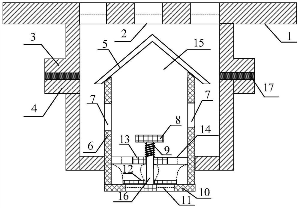
[0029] like figure 1 Shown, a kind of insulation breathing manhole cover for air valve, comprises:
[0030] The well cover 1 is provided with a plurality of first ventilation holes 2, and a cylindrical support structure is provided under the well cover 1. A cavity 15 is provided inside the support structure, and a cylindrical inner cylinder 6 is provided inside the support structure. A plurality of second ventilation holes 7 are provided on the cylinder wall of the cylinder 6, a base plate 10 is provided at the bottom of the inner cylinder 6, a cylinder 16 is provided at the center of the base plate 10, and a plurality of third ventilation holes 11 are arranged on the bottom plate 10, above the third ventilation hole 11 A ring-shaped baffle 12 is provided, an upper plate 8 is arranged above the cylinder 16, and a middle partition 13 is arranged between the upper board 8 and the bottom plate 10. The middle partition 13 is provided with a plurality of fourth ventilation holes 14...
Embodiment 2
[0040] A method for using an insulating breathing manhole cover for an air valve, comprising the following steps:
[0041] Closed state: the bottom plate 10 of the inner cylinder 6 maintains an airtight state with the wall of the inner cylinder 6 under the tension of the spring 9, and at the same time, the ring-shaped cover plate 12 seals some third ventilation holes on the bottom plate 10 under the action of gravity. 11 closed, the manhole cover is closed;
[0042] Exhaust state: the air valve starts to exhaust, the pressure under the bottom plate 10 is greater than the pressure of the cavity 15, the annular cover plate 12 is lifted, and the pressurized gas passes through the third vent hole 11, the fourth vent hole 14, and the second vent hole in sequence 7 and the first ventilation hole 2 are discharged in the well;
[0043] Inhalation state: the air valve starts to inhale, the pressure under the bottom plate 10 is lower than the pressure of the cavity 15, the spring 9 is ...
PUM
 Abstract
Description
Claims
Application Information