Thrust structure of compressor and rotor type compressor

A compressor and thrust seat technology, applied in the field of compressors, can solve the problems of low input power of the thrust structure on the end face of the short shaft of the crankshaft, low power of the eccentric part-cylinder head thrust structure, etc., so as to reduce the thrust wear and improve the Service life, the effect of improving the life of the pump body

Pending Publication Date: 2021-12-31
SHANGHAI HITACHI ELECTRICAL APPLIANCES CO LTD
View PDF0 Cites 0 Cited by
  • Summary
  • Abstract
  • Description
  • Claims
  • Application Information

AI Technical Summary

Problems solved by technology

from figure 2 It can be seen from the figure that the input power of the crankshaft short shaft end face thrust structure is low in the low-speed and high-speed sections, and the power of the eccentric part-cylinder head thrust structure is low in the medium-speed section

Method used


Image

  • Thrust structure of compressor and rotor type compressor
  • Thrust structure of compressor and rotor type compressor
  • Thrust structure of compressor and rotor type compressor

Examples


Embodiment Construction

[0046] Example embodiments will now be described more fully with reference to the accompanying drawings. Example embodiments may, however, be embodied in many forms and should not be construed as limited to the examples set forth herein; rather, these embodiments are provided so that this disclosure will be thorough and complete and will fully convey the concept of example embodiments to those skilled in the art. The described features, structures, or characteristics may be combined in any suitable manner in one or more embodiments.

[0047] Furthermore, the drawings are merely schematic illustrations of the present disclosure and are not necessarily drawn to scale. The same reference numerals in the drawings denote the same or similar parts, and thus repeated descriptions thereof will be omitted. Some of the block diagrams shown in the drawings are functional entities and do not necessarily correspond to physically or logically separate entities.

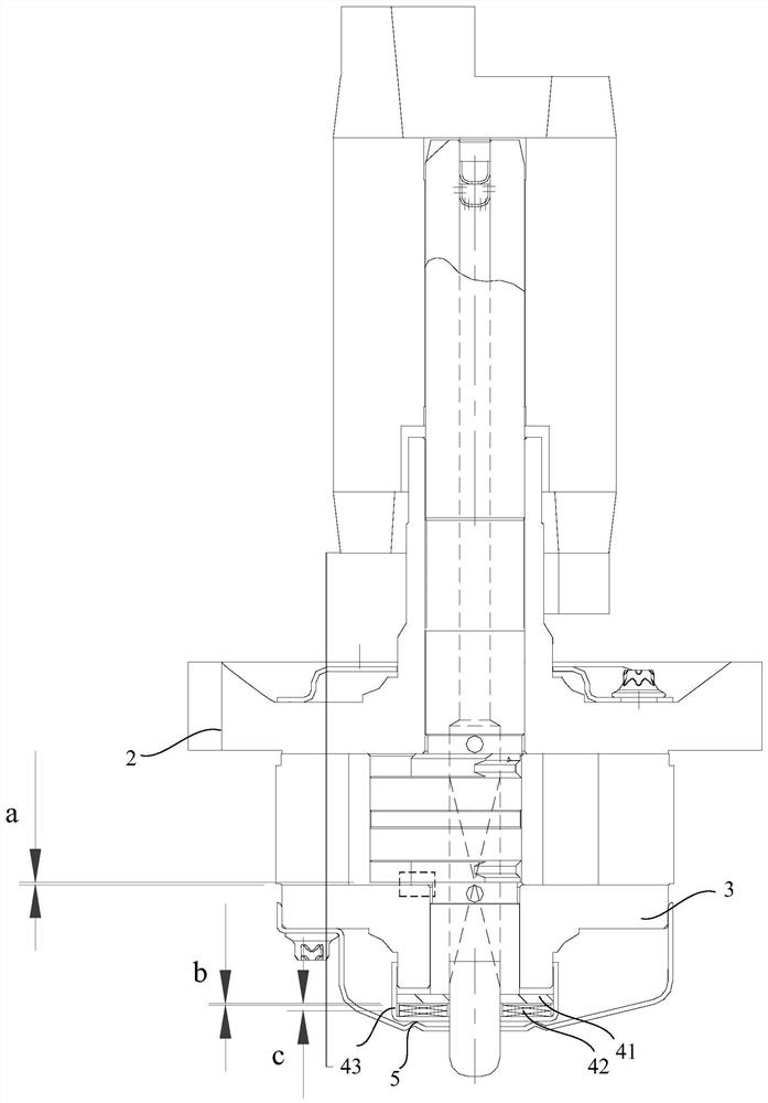
[0048] image 3 It is a...


PUM


Abstract

The invention provides a thrust structure of a compressor and a rotor type compressor comprising the thrust structure. The thrust structure comprises a main bearing and an auxiliary bearing, a crankshaft, a first thrust structure and a second thrust structure; the main bearing and the auxiliary bearing jointly limit a compression space with an air cylinder of the compressor, and the main bearing is located between a motor and the air cylinder; the crankshaft is provided with a long shaft part, an eccentric part and a short shaft part, the crankshaft transmits the rotating force of the motor to the air cylinder to compress the refrigerant, and the auxiliary bearing is located below the eccentric part of the crankshaft and supports the short shaft part of the crankshaft; the first thrust structure comprises a thrust plate, an elastic assembly and a thrust seat, and the thrust plate, the elastic assembly and the thrust seat are sequentially arranged on the short shaft part abutting against the lower end face of the auxiliary bearing in a sleeving mode; the second thrust structure is composed of the lower end face of the eccentric part of the crankshaft and the upper end face of the auxiliary bearing, and in the initial state, the lower end face of the eccentric part of the crankshaft and the upper end face of the auxiliary bearing are oppositely arranged, and a gap is formed between the lower end face of the eccentric part of the crankshaft and the upper end face of the auxiliary bearing. According to the thrust structure, thrust abrasion can be effectively relieved, and the service life of a compressor pump body and the service life of a whole machine are prolonged.

Description

technical field [0001] The invention relates to the field of compressors, in particular to a thrust structure of a compressor and a rotary compressor including the thrust structure. Background technique [0002] Existing rotary compressors generally adopt a vertical structure. The crankshaft 1 of the compressor has a long axis portion 11, an eccentric portion 12, and a short axis portion 13. The crankshaft 1 transmits the rotational force of the motor to the cylinder to compress and refrigerate. agent, see figure 1 . Due to the gravity of the crankshaft 1 itself, the gravity of the motor rotor fixed on its long axis, and the electromagnetic downforce caused by the height difference of the magnetic core, an upward reverse thrust balance is required to maintain a relatively static state in the axial direction. At present, the commonly used axial thrust structure has the following two types: [0003] a. Use the shoulder position of the eccentric part of the crankshaft to thr...

Claims


Application Information

Patent Timeline
IPC IPC(8): F04C29/00F04C23/02F04C29/02
CPCF04C29/00F04C29/0021F04C23/02F04C29/02F04C2240/601F04C2240/50F04C2240/80
Inventor 匡勇军周忆万古强应哲强
Owner SHANGHAI HITACHI ELECTRICAL APPLIANCES CO LTD
Why Eureka
Try Eureka