Positioning device for cutting optical fiber patch cord

A technology for optical fiber jumpers and positioning devices, which is applied in the coupling of optical waveguides, etc., can solve problems such as fiber jumper looseness, and achieve the effects of avoiding eversion, improving buffer protection performance, and avoiding damage

Pending Publication Date: 2021-12-31
深圳市和光同诚科技有限公司
View PDF1 Cites 0 Cited by
  • Summary
  • Abstract
  • Description
  • Claims
  • Application Information

AI Technical Summary

Problems solved by technology

[0005] The main purpose of the present invention is to provide a positioning device for cutting optical fiber jumpers to solve the problem that the optical fiber jumpers are in a loose state at the cutting table

Method used


Image

  • Positioning device for cutting optical fiber patch cord
  • Positioning device for cutting optical fiber patch cord
  • Positioning device for cutting optical fiber patch cord

Examples


Embodiment 1

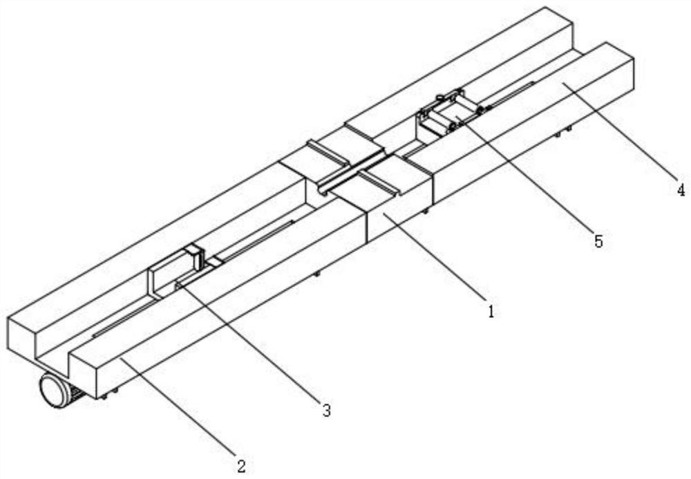
[0035] Such as figure 1 , 2 , 3, 4, 5, 6, 7, and 8, a positioning device for cutting optical fiber jumpers, including a cutting table 1, a first bracket 2 with a driving device and a length adjustment device 3, the first The support 2 with driving device comprises a first support frame 201 and a first chute 202, the upper end of the first support frame 201 is provided with a first chute 202, and one end of the first support frame 201 is provided with a cutting table 1, and the length is adjusted The device 3 includes a first sliding seat 301 and a joint slot 302, the first sliding seat 301 is provided in the first sliding slot 202, and the upper end of the first sliding seat 301 is provided with a joint slot 302;

[0036] The other end of the cutting table 1 is provided with a second support 4 with a driving device, and the second support 4 with a driving device includes a second support frame 401, a second chute 402, a second ball screw 403 and a second connector 404, the o...

Embodiment 2

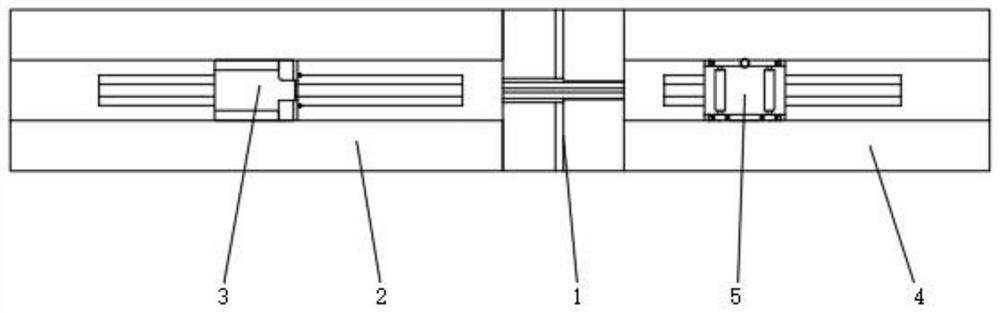
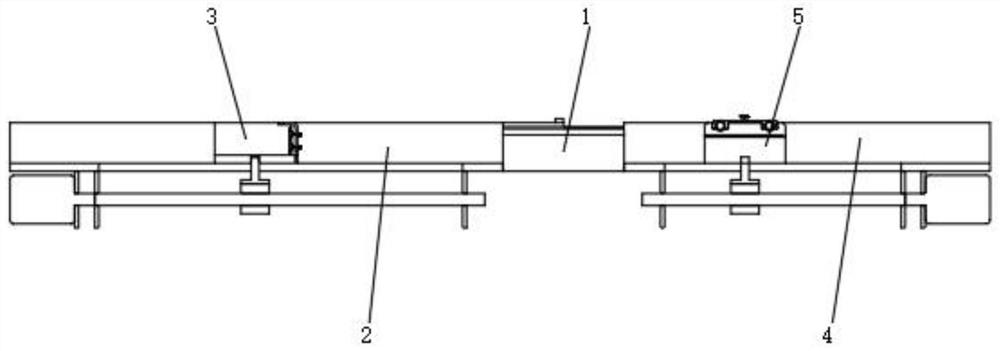
[0041] Such as image 3 , 4 , 5, and 8, wherein the same or corresponding components as those in Embodiment 1 use the corresponding reference numerals as in Embodiment 1. For the sake of simplicity, only the differences from Embodiment 1 will be described below. The difference is that the first bracket 2 with the driving device also includes a first ball screw 203 and a first connector 204, the lower end of the first support frame 201 is provided with a first ball screw 203, and the first ball screw The moving part of 203 is connected with a first connector 204, and the first connector 204 is inserted into the first chute 202 and connected with the first sliding seat 301;

[0042] The length adjustment device 3 also includes a U-shaped piece 303, a blocking piece 304, a movable rod 305, a back-moving spring 306, a fixed piece 307 and a buffer pad 308, and the other side of the first sliding seat 301 is provided with a U-shaped piece 303, and the U-shaped piece A stopper 304 ...


PUM


Abstract

The invention relates to the technical field of optical fiber patch cord production, in particular to a positioning device for cutting an optical fiber patch cord, and aims to solve the problem that the optical fiber patch cord is in a loose state at a cutting table. A second bracket with a driving device is arranged at one end of the cutting table; the second support with the driving device comprises a second supporting frame, a second sliding groove, a second ball screw and a second connector. A second supporting frame is arranged at the other end of the cutting table, and a second sliding groove is formed in the upper end of the second supporting frame. A second ball screw is arranged at the lower end of the second support frame; the upper end of a moving part of the second ball screw is connected with a second connector; the second connector is inserted into the second sliding groove and connected with a straightening device. The optical fiber patch cord is clamped through the cooperation of the extrusion rod, the fixing block, the fastening bolt and the second sliding seat, and the optical fiber patch cord is straightened through the cooperation of the second ball screw, the second connector and the second sliding seat, so that the optical fiber patch cord is prevented from loosening during cutting.

Description

technical field [0001] The invention relates to the technical field of production of optical fiber jumpers, in particular to a positioning device for cutting optical fiber jumpers. Background technique [0002] The Chinese utility model patent application number is CN202022257251.1, and the patent name is a positioning device for cutting optical fiber jumpers. A positioning block that defines the cutting position of the cutter; a slide rail that is installed on the top surface of the base along a first direction, and one end of the slide rail is closely attached to the side wall of the boss and points to the position defined by the positioning block Cutting position; slider, which is slidably installed on the slide rail, and a fixing groove for fixing the optical fiber jumper connector is recessed on the slider, and one end of the fixing groove adjacent to the positioning block is provided with a fiber optic The first positioning slot through which the jumper optical cable ...

Claims


Application Information

Patent Timeline
Patent Type & Authority Applications(China)
IPC IPC(8): G02B6/25
CPCG02B6/25
Inventor 田玉川黄鹏
Owner 深圳市和光同诚科技有限公司
Why Eureka
Try Eureka