Check patentability & draft patents in minutes with Patsnap Eureka AI!

Transformer demagnetization method and related assembly

A transformer and demagnetization technology, applied in the field of transformers, can solve the problems of transformers that cannot be completely demagnetized, large current short circuit, and cannot be demagnetized

Pending Publication Date: 2021-12-31
HANGZHOU ELECTRIC EQUIP MFG +2
View PDF0 Cites 0 Cited by
  • Summary
  • Abstract
  • Description
  • Claims
  • Application Information

AI Technical Summary

Problems solved by technology

[0002] The electrical industry has been extensively developed to the present, and the transformer is the main power component of the transmission and distribution part. When the power system fails, or the switching timing of the switch is inappropriate, it may cause a DC component on the secondary side of the transformer, resulting in a large current short circuit , which in turn causes the transformer core to saturate
Most of the existing solutions are the fixed switch resistance demagnetization method, that is, a resistor with a fixed resistance value is set on the secondary side of the transformer. When there is a DC component in the secondary side coil, the current signal on the secondary side will exist and magnetically communicate. In the case of different signal directions, the conduction of the circuit where the fixed resistance resistor is located will consume the DC component in the secondary side coil of the transformer to achieve demagnetization
[0003] However, the parameters of different transformers are different, and the magnitude of the DC component in the secondary side coil is also different. A resistor with a fixed resistance may cause the transformer to be unable to demagnetize completely, or to demagnetize at all.

Method used


Image

  • Transformer demagnetization method and related assembly
  • Transformer demagnetization method and related assembly
  • Transformer demagnetization method and related assembly

Examples


Embodiment Construction

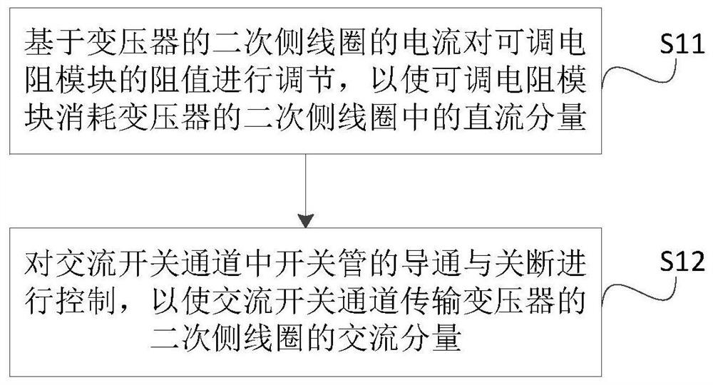
[0043] The core of the present invention is to provide a transformer demagnetization method and related components. By setting an adjustable resistance module, not only the demagnetization of the secondary side coil of the transformer can be realized, but also the current pair of the secondary side coil of the transformer can be adjusted. The resistance value of the resistance module is adjusted to meet the demagnetization requirements of different transformers, which saves costs.

[0044] In order to make the purpose, technical solutions and advantages of the embodiments of the present invention clearer, the technical solutions in the embodiments of the present invention will be clearly and completely described below in conjunction with the drawings in the embodiments of the present invention. Obviously, the described embodiments It is a part of embodiments of the present invention, but not all embodiments. Based on the embodiments of the present invention, all other embodime...


PUM


Abstract

The invention discloses a transformer demagnetization method and a related assembly thereof, a transformer demagnetization device comprises a current detection module, an adjustable resistor module and an alternating current switch channel, and the resistance value of the adjustable resistor module is adjusted based on the current of a secondary side coil of a transformer. The adjustable resistor module consumes a direct current component in a secondary side coil of the transformer, so that the secondary side coil of the transformer is demagnetized; in addition, the switch-on and switch-off of a switch tube in the alternating current switch channel are controlled, so that the alternating current switch channel transmits the alternating current component of the secondary side coil of the transformer. Therefore, by arranging the adjustable resistor module, demagnetization of the secondary side coil of the transformer can be achieved, the resistance value of the adjustable resistor module can be adjusted according to the current of the secondary side coil of the transformer so as to meet the demagnetization requirements of different transformers, and cost is saved.

Description

technical field [0001] The invention relates to the field of transformers, in particular to an electrical method for demagnetizing a transformer and related components. Background technique [0002] The electrical industry has been extensively developed to the present, and the transformer is the main power component of the transmission and distribution part. When the power system fails, or the switching timing of the switch is inappropriate, it may cause a DC component on the secondary side of the transformer, resulting in a large current short circuit , which in turn leads to saturation of the transformer core. Most of the existing solutions are the fixed switch resistance demagnetization method, that is, a resistor with a fixed resistance value is set on the secondary side of the transformer. When there is a DC component in the secondary side coil, the current signal on the secondary side will exist and magnetically communicate. In the case of different signal directions,...

Claims


Application Information

Patent Timeline
IPC IPC(8): H01F13/00
CPCH01F13/00
Inventor 邢海青姚海燕陆斌黄元君沈毅姚程高阮建平胡宇凯
Owner HANGZHOU ELECTRIC EQUIP MFG
Features
  • R&D
  • Intellectual Property
  • Life Sciences
  • Materials
  • Tech Scout
  • Unparalleled Data Quality
  • Higher Quality Content
  • 60% Fewer Hallucinations
Learn More