Check patentability & draft patents in minutes with Patsnap Eureka AI!

Control device and method for controlling separately excited rotor windings of synchronous machines

A rotor winding and control device technology, applied in the direction of controlling the generator, controlling the generator through the change of the magnetic field, controlling the system, etc., can solve the problems of inefficiency, not very fast demagnetization, etc.

Inactive Publication Date: 2015-09-23
BRUSA ELECTRONICS AG
View PDF6 Cites 0 Cited by
  • Summary
  • Abstract
  • Description
  • Claims
  • Application Information

AI Technical Summary

Problems solved by technology

[0009] Although known solutions are suitable for specific applications or specific conditions, the fact that demagnetization does not occur very quickly or efficiently according to the prior art is problematic
However, especially when synchronous motors are used in electric vehicle constructions, these limitations are often unacceptable

Method used


Image

  • Control device and method for controlling separately excited rotor windings of synchronous machines
  • Control device and method for controlling separately excited rotor windings of synchronous machines
  • Control device and method for controlling separately excited rotor windings of synchronous machines

Examples


Embodiment Construction

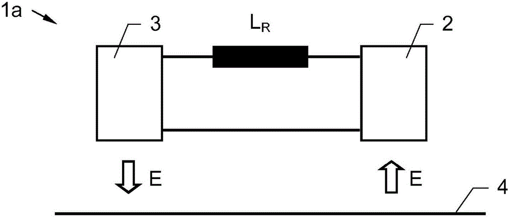
[0037] figure 1 A first variant of the system 1a according to the invention is shown, consisting of a control device and a synchronous motor connected to the control device. The figure is greatly simplified, therefore, only one separately excited rotor winding L of the synchronous machine is shown R . Used to transfer the electrical energy E from the power source 4 to the rotor winding L R A voltage source 2 is connected to the rotor winding as part of the control unit. According to the invention, the control device also includes a R and is used to transfer electrical energy E from the rotor winding L R The electric device 3 transmitted to the power source 4.

[0038] exist figure 1 The functionality of the device shown in is described below.

[0039] If the electrical energy E from the power source 4 is fed to the rotor winding L via the voltage source 2 R , then the rotor winding L R is excited or magnetized, and the rotating magnetic field generated in the stator w...


PUM


Abstract

A control device for a separately excited rotor winding (LR) of a synchronous machine is described, which comprises a voltage source (2) connected to the rotor winding (LR) and intended for transmitting electrical energy (E) from a power supply (4) to the rotor winding (LR), in such a way that said rotor winding is caused to rotate by a rotating field on the stator side. According to the invention, the control device furthermore comprises a consumer (3) connected to the rotor winding (LR) and intended for transmitting electrical energy (E) from the rotor winding (LR) to the power supply (4). Furthermore, a method for controlling a separately excited rotor winding (LR) of a synchronous machine is described.

Description

technical field [0001] The invention relates to a control device for a separately excited rotor winding of a synchronous machine, comprising a voltage source connected to the rotor winding for transferring electrical energy from the source to the rotor winding by means of a The rotating magnetic field rotates the rotor windings. Furthermore, the invention relates to a method for controlling a separately excited rotor winding of a synchronous machine, wherein electrical energy from a power source is fed to the rotor winding via a voltage source connected to said rotor winding by means of The rotating magnetic field on the stator side rotates the rotor windings. Background technique [0002] Synchronous electrical machines have been known for a long time and are used for a very wide variety of purposes both as generators and as electric motors. As brushless DC motors, they also occupy a large area in DC drive technology. The AC voltage for stator excitation is generated fro...

Claims


Application Information

Patent Timeline
IPC IPC(8): H02P9/12H02P9/14H02P9/30H02P9/38
CPCH02P9/30H02P9/12H02P9/38H02P9/14H02P9/302H02P9/123
Inventor A·克劳泽
Owner BRUSA ELECTRONICS AG
Features
  • R&D
  • Intellectual Property
  • Life Sciences
  • Materials
  • Tech Scout
  • Unparalleled Data Quality
  • Higher Quality Content
  • 60% Fewer Hallucinations
Learn More