Check patentability & draft patents in minutes with Patsnap Eureka AI!

A method and device for demagnetizing a ferromagnetic elongated member

A slender component, ferromagnetic technology, applied in the field of electromagnetic non-destructive testing of ferromagnetic components, can solve the problems of complex overall structure of the device, difficult heating, inconvenient operation, etc., and achieve the effects of simple structure, convenient demagnetization, and convenient operation

Active Publication Date: 2017-05-10
HUAZHONG UNIV OF SCI & TECH
View PDF5 Cites 0 Cited by
  • Summary
  • Abstract
  • Description
  • Claims
  • Application Information

AI Technical Summary

Problems solved by technology

Among them, heating demagnetization is to heat the magnet member above the Curie temperature of the member, and then place it in an environment without an external magnetic field to cool slowly, so that the magnetic domains in the member can re-orientate and distribute freely to demagnetize the member. In practice, for steel It is difficult to heat slender ferromagnetic components such as rods and wire ropes, and there are problems such as inconvenient operation for demagnetization by this method; while AC demagnetization, DC demagnetization, and AC-DC composite demagnetization mostly use energized coils to generate demagnetization magnetic fields, which require specific AC and DC power supplies and Commutation circuit, and generally demagnetize the ferromagnetic slender member by passing the ferromagnetic slender member through the coil along the coil axis direction, which requires a corresponding feeding mechanism and supporting devices. The overall structure of the device is complex and inconvenient to operate, and higher cost

Method used


Image

  • A method and device for demagnetizing a ferromagnetic elongated member
  • A method and device for demagnetizing a ferromagnetic elongated member
  • A method and device for demagnetizing a ferromagnetic elongated member

Examples


specific Embodiment

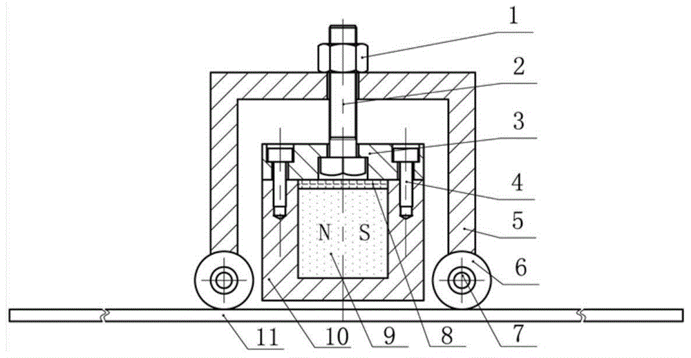
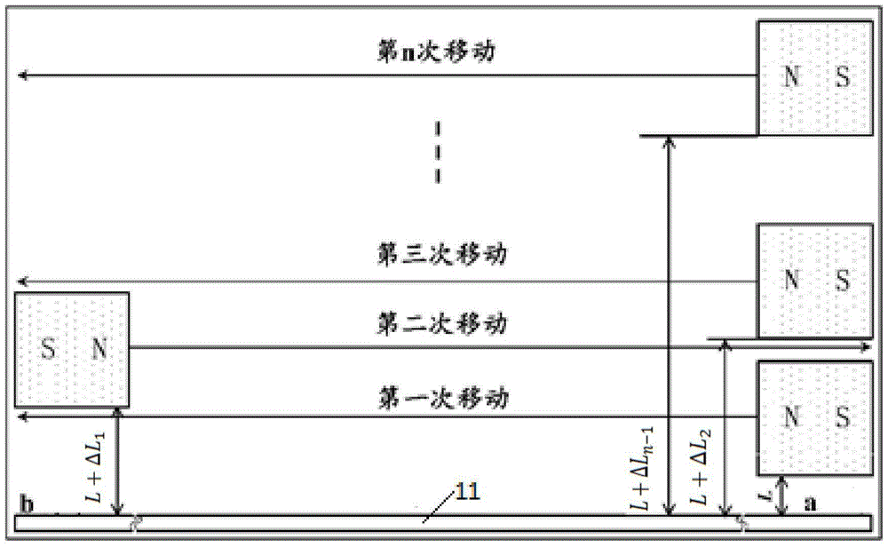
[0039] The present embodiment adopts three steel rods with an outer diameter of 20 mm and a length of 1 m as demagnetization objects, respectively measure the axial residual magnetic induction intensity at the ends of steel rods a and b before demagnetization, and steel rods a and b after demagnetization using the method described in the present invention. The axial residual magnetic induction intensity at the b end is used to analyze and illustrate the demagnetization effect of the method of the present invention, and the direction of the magnetic induction intensity is defined as positive to the right, and the measurement results are as shown in Table 1.

[0040] It specifically includes the following steps:

[0041] 1) According to the ferromagnetic slender member to be demagnetized, the permanent magnet used to provide the magnetic field is selected mainly according to the residual magnetic strength, coercive force and cross-sectional size of the member, and the performance...


PUM


Abstract

The invention discloses a method and a device for demagnetizing a ferromagnetic elongated member. According to the method, a permanent magnet is utilized to carry out a reciprocating motion in a quasi demagnetization region of the member along the member; the magnetic pole direction of the permanent magnet is reversely arranged during each reciprocating motion; lift-off from the permanent magnet and the surface of the member is increased; and the permanent magnet is in repeated reciprocating motions until the lift-off to the member is large enough, so that the remanence attenuation in the member is zero to finish demagnetization of the member. The demagnetizing device comprises a magnet assembly, a motion assembly and a lift-off assembly, wherein the magnet assembly is used for generating a magnetic field for demagnetization; the motion assembly is used for achieving the reciprocating motion of the magnet assembly; and the lift-off assembly is used for adjusting the lift-off of the magnet assembly relative to the elongated member. According to the method and the device, a complicated feeding device is not needed; and the device is convenient to operate, simple in structure and good in demagnetization effect, can be applied to demagnetization of remanent fields of ferromagnetic structures of steel bars, wire ropes, cables and the like.

Description

technical field [0001] The invention belongs to the field of electromagnetic non-destructive testing of ferromagnetic components, and more specifically relates to a demagnetization method and device for ferromagnetic slender components. Background technique [0002] Magnetic nondestructive testing is widely used in the detection of cracks, corrosion and stress of ferromagnetic components. During magnetic testing, the component needs to be magnetized, and residual magnetism will inevitably exist in the component after the test is completed; residual magnetism may affect the next test result, affect the working accuracy of the instrument, and may also cause magnetic deflection during electric welding. Therefore, it is very necessary to demagnetize the ferromagnetic member after magnetic detection, especially the ferromagnetic elongated member. [0003] At present, the commonly used demagnetization methods of ferromagnetic components mainly include heating demagnetization, AC ...

Claims


Application Information

Patent Timeline
Patent Type & Authority Patents(China)
IPC IPC(8): H01F13/00
Inventor 武新军邓东阁
Owner HUAZHONG UNIV OF SCI & TECH
Features
  • R&D
  • Intellectual Property
  • Life Sciences
  • Materials
  • Tech Scout
  • Unparalleled Data Quality
  • Higher Quality Content
  • 60% Fewer Hallucinations
Learn More