Mechanical foot

A technology of mechanical foot and angle, applied in the field of mechanical foot, can solve the problem of easy fall of patients, and achieve the effect of reducing patient discomfort and the possibility of tripping

Pending Publication Date: 2022-01-04
ANGELEXO SCI CO LTD
View PDF1 Cites 1 Cited by
  • Summary
  • Abstract
  • Description
  • Claims
  • Application Information

AI Technical Summary

Problems solved by technology

[0005] The purpose of the present invention is to provide a mechanical foot to solve the problem that patients are prone to fall in the background technology

Method used


Image

  • Mechanical foot
  • Mechanical foot
  • Mechanical foot

Examples


Embodiment 1

[0032] The present embodiment provides a mechanical ankle joint comprising a leg portion for securing to the patient's leg and a foot portion for securing to the patient's foot, the two portions They can be connected with each other, so that people who have lost their walking function can walk or perform rehabilitation training. They are especially suitable for patients with hemiplegia, or people with lower limbs who are paralyzed for lower limb rehabilitation training. The lower limb paralysis or half paralysis here is mainly because the lower limbs are not controlled by the brain nerves, and through rehabilitation training, patients who can restore nerve control wear mechanical feet. In some embodiments, the articulation here is a rotational connection, and the mechanical ankle joint includes a rotational joint so that the leg portion and the foot structure portion can rotate relative to each other. In some approaches, the foot portion is secured to the patient's foot by con...

Embodiment 2

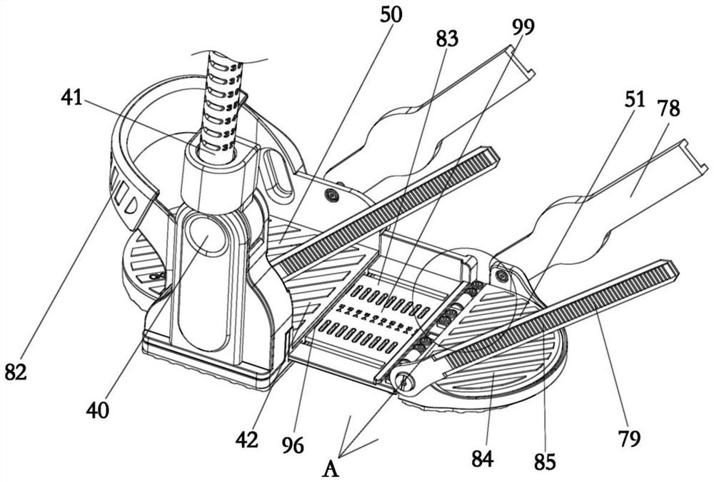
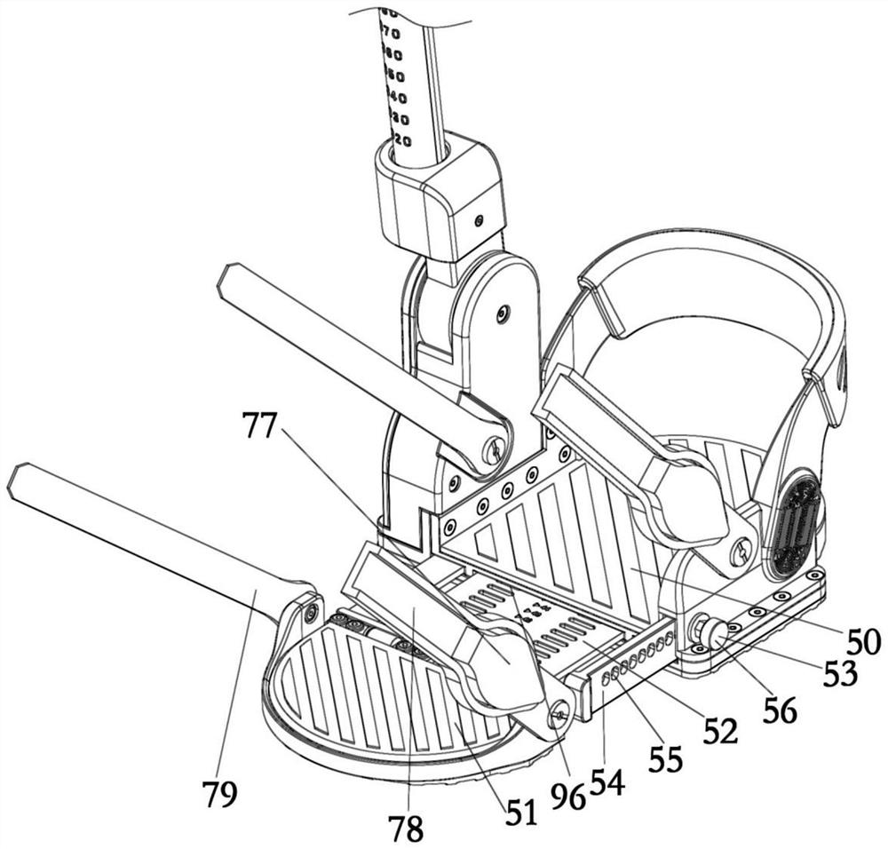
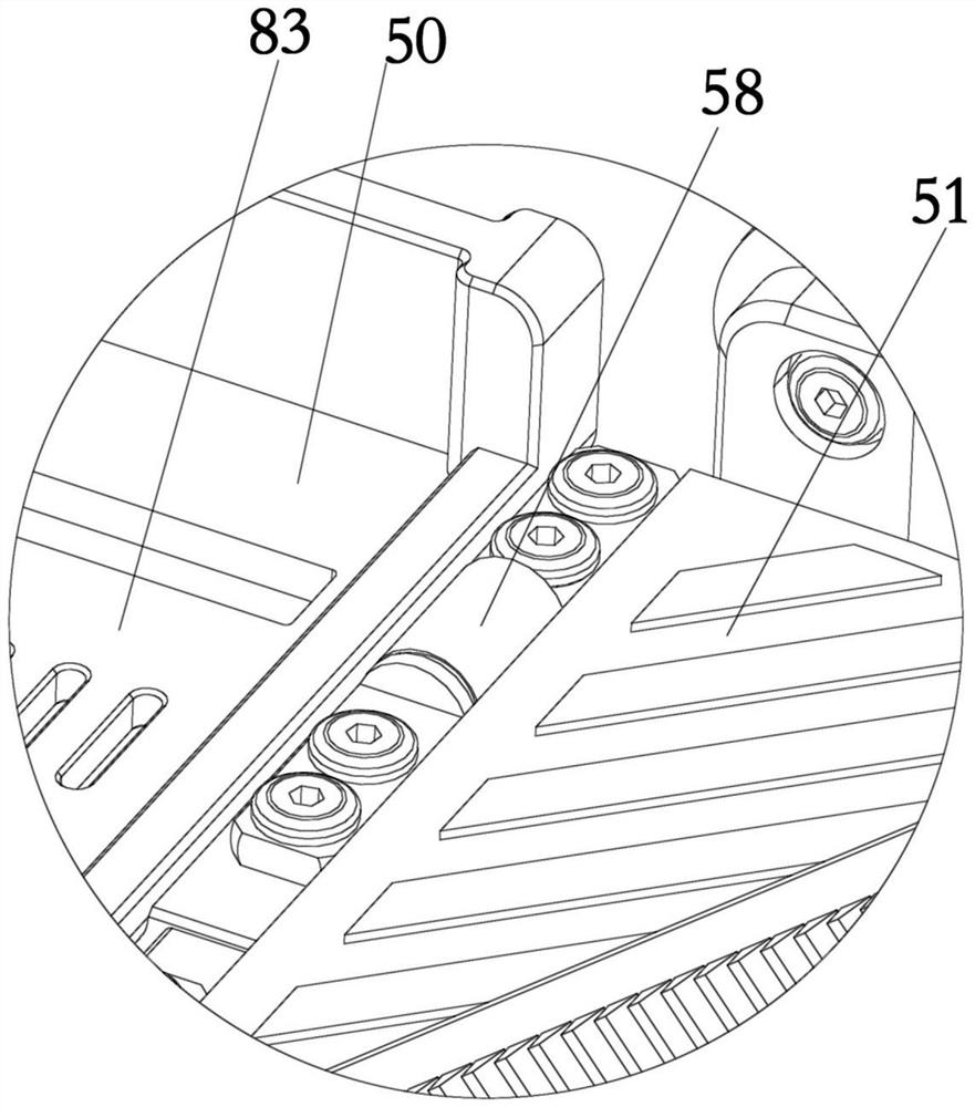
[0044] This embodiment provides a shoe with adjustable wearing size, including a first part 50 and a second part 51. The first part 50 and the second part 51 constitute the bottom surface on which the foot of the patient steps on in Embodiment 1, and the patient's foot can step on it. On the first part 50 and the second part 51, due to the different foot sizes of different patients, in order to enhance the adaptability of the shoes to the patient, the first part 50 is movably connected with the second part 51, by adjusting the first part 50 and the second part of the activity The relative position of 51 makes the length of the sole stepped on by the adjusted foot match the patient's foot. Specifically, a slidable connecting plate 52 is provided between the first part 50 and the second part 51, and the connecting plate 52 is connected with one of the first part 50 and the second part 51, and embedded in the other, the connecting plate 52 is also provided with a second locking s...

Embodiment 3

[0049] Embodiment 3, with reference to attached Figure 9 .

[0050] The traditional mechanical foot has a leg part 41 and a stepping bottom surface 99. The leg part 41 is used to connect the patient's leg, and the stepping bottom surface 99 is used to fit the patient's sole. When in use, the leg part 41 is fixed to On the patient's leg, the patient's foot steps on the bottom surface 99, but the axis of the leg part 41 in the traditional mechanical foot is perpendicular to the plane where the bottom surface 99 is located, which makes the patient feel uncomfortable when wearing the mechanical foot. A feeling of turning the foot inward, which can cause discomfort. The present embodiment provides a mechanical foot, which also includes a leg portion 41 and a step-on bottom surface 99, wherein the axis of the leg portion 41 is not perpendicular to the plane where the step-on bottom surface 99 is located, which conforms to the ergonomic design, allowing the patient to wear the mech...


PUM


Abstract

The invention provides a mechanical foot. The mechanical foot comprises a third part and a second part; an included angle is formed between the third part and the second part, the included angle is an obtuse angle or a flat angle, and the included angle between the third part and the second part is adjustable; after the included angle between the third part and the second part is adjusted, the included angle can be kept at a fixed angle; and the included angle between the third part and the second part is unadjustable. The front sole of the affected side of a patient can be lifted in the walking process of the patient, and therefore foot dragging and some injuries caused by stumbling or falling related to foot dragging are prevented.

Description

technical field [0001] The invention relates to the technical field of medical devices, in particular to a mechanical foot. Background technique [0002] Patients with weakened lower extremities, such as patients after a stroke, have uncontrolled or uncontrollable movements on one side of the affected extremity. For these reasons, when lifting the leg, the foot position of these patients is always different. Under the action of its own gravity, it naturally sags around the ankle joint. It is important to prevent foot drop as these patients are at risk of dragging their foot on the ground while walking, tripping, and falling if the problem of foot drop is not addressed. [0003] The Chinese patent with the authorized notification number CN105722490B provides a device that can reliably lift a person's toes during the swing of the lower limbs. The ankle strap is provided with a retractable elastic element, which is connected to the foot through a cable and swings in the lower ...

Claims


Application Information

Patent Timeline
Patent Type & Authority Applications(China)
IPC IPC(8): A61H3/00A61F5/01
CPCA61F5/0127A61F2005/0179A61H3/00A61H2003/007A61H2201/165A61H2201/1642A61H2205/12A61H1/0266A61H2201/14A61H2201/1671A61H2201/1261A61H2201/164A61H2201/0165A61H2201/0192
Inventor 樊炎军常永杰王孝泽王俞兵杨森陈雪华李鲁亚
Owner ANGELEXO SCI CO LTD
Why Eureka
Try Eureka