Traditional Chinese medicine acupuncture and moxibustion human body acupuncture point locator
A locator and acupuncture technology, which are used in physical therapy positioning, instruments for determining reflex points, acupuncture and other directions, which can solve the problem of inconvenient patient's hand or leg placement, inability to achieve heat therapy, and inconvenience for accurate acupoint positioning, etc. problem, to achieve convenient and accurate acupuncture, good effect, and improve the effect of acupuncture
- Summary
- Abstract
- Description
- Claims
- Application Information
AI Technical Summary
Problems solved by technology
Method used
Image
Examples
Embodiment 1
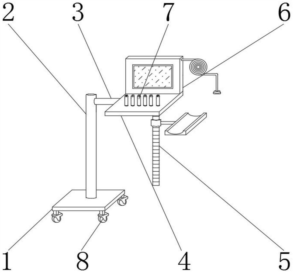
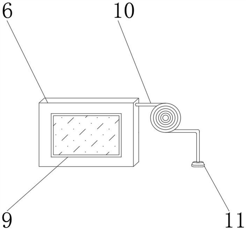
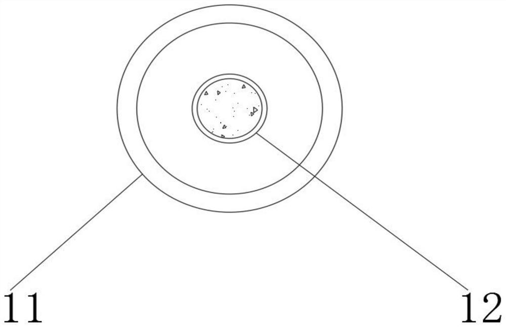
[0022] Such as Figure 1-3 As shown, a Chinese acupuncture and moxibustion human body acupoint locator includes a base plate 1, a main rod 2 is arranged on the outer surface of the upper end of the base plate 1, an auxiliary rod 3 is arranged on the outer wall of the main rod 2, and a placement plate is arranged on the outer surface of one end of the auxiliary rod 3 4. The outer surface of the lower end of the placement plate 4 is provided with a supporting mechanism 5, and the outer surface of the upper end of the bottom plate 1 is provided with a pulse locator 6 and a heat therapy mechanism 7. The pulse locator 6 is located on one side of the heat therapy mechanism 7, and the bottom plate 1 The outer surface of the lower end is provided with a moving wheel 8, the outer surface of the front end of the pulse locator 6 is provided with a touch screen 9, the outer surface of one side of the pulse locator 6 is provided with a conductive line 10, and the outer surface of one end of...
Embodiment 2
[0024] On the basis of Example 1, such as Figure 4 As shown, the supporting mechanism 5 includes a threaded rod 501, a rotating sleeve 502, a connecting rod 503 and a drag-and-drop plate 504. On the outer surface of one end of the connecting rod 503, a thread is provided between the threaded rod 501 and the rotating sleeve 502, the outer wall of the threaded rod 501 is movably connected with the inner wall of the rotating sleeve 502 through threads, and the outer wall of the rotating sleeve 502 is connected to the outer surface of the other end of the connecting rod 503. The surface is welded and connected, and the outer surface of one end of the connecting rod 503 is welded and connected with the outer surface of one side of the drag and drop plate 504. The support mechanism 5 can support and place the patient's hands or legs through the drag and drop plate 504 during use. When in use, it is convenient to perform acupuncture treatment on the patient's legs or hands.
Embodiment 3
[0026] On the basis of Example 1, such as Figure 5 , 6 As shown, the thermotherapy mechanism 7 includes a heating cylinder 701, a control box 702, an annular suction cup 703, a through hole 704, a control switch 705 and a warm lamp ring 706. The control box 702 is located on the outer surface of one end of the heating cylinder 701, and the annular suction cup 703 is located On the outer surface of the other end of the cylinder 701, the through hole 704 is located on the outer surface of one end of the control box 702, the control switch 705 is located on the outer wall of the control box 702, the warm lamp ring 706 is located in the middle of the heating cylinder 701, between the heating cylinder 701 and the control box 702 A first buckle is provided, and the outer surface of one end of the heating cylinder 701 is detachably connected to the outer surface of the other end of the control box 702 through the first buckle. The control box 702 and the through hole 704 are integra...
PUM
 Abstract
Description
Claims
Application Information
 - R&D
- Intellectual Property
- Life Sciences
- Materials
- Tech Scout
- Unparalleled Data Quality
- Higher Quality Content
- 60% Fewer Hallucinations
Browse by: Latest US Patents, China's latest patents, Technical Efficacy Thesaurus, Application Domain, Technology Topic, Popular Technical Reports.
© 2025 PatSnap. All rights reserved.Legal|Privacy policy|Modern Slavery Act Transparency Statement|Sitemap|About US| Contact US: help@patsnap.com


