
Vehicle-mounted spare tire storage rack

A storage rack and vehicle-mounted technology, which is applied in the layout of spare tires, vehicle components, transportation and packaging, etc., can solve the problems of inability to meet the general design requirements of spare tire mounting brackets, poor versatility, and uneven stress on the spare tire.

Inactive Publication Date: 2022-01-04
安徽正特机电科技有限公司
View PDF10 Cites 0 Cited by
  • Summary
  • Abstract
  • Description
  • Claims
  • Application Information

AI Technical Summary

Problems solved by technology

The product quality of the spare tire mounting mechanism with this structure is often difficult to guarantee, especially the main struts, auxiliary struts and support plates of the spare tire bracket often have excessive contact with the rim during the process of compressing the spare tire, causing the rim to be squeezed and damaged. damage problem
[0003] Secondly, installing the spare tire through the spare tire bracket also has potential risks caused by uneven stress on the spare tire
Not only that, the generality of the traditional spare tire mounting mechanism is poor, and a spare tire rack can match fewer tire models; there is only a corresponding relationship between the existing spare tire mounting The bracket can only be used for the installation of one type of spare tire, and cannot match the installation of multiple types of spare tires, and cannot meet the general design requirements of the spare tire mounting bracket

Method used


Image

  • Vehicle-mounted spare tire storage rack
  • Vehicle-mounted spare tire storage rack
  • Vehicle-mounted spare tire storage rack

Examples


Embodiment Construction

[0027] The following will clearly and completely describe the technical solutions in the embodiments of the present invention with reference to the accompanying drawings in the embodiments of the present invention. Obviously, the described embodiments are only some, not all, embodiments of the present invention. Based on the embodiments of the present invention, all other embodiments obtained by persons of ordinary skill in the art without creative efforts fall within the protection scope of the present invention.

[0028] In describing the present invention, it is to be understood that the terms "opening", "upper", "lower", "thickness", "top", "middle", "length", "inner", "surrounding" etc. Indicating orientation or positional relationship is only for the convenience of describing the present invention and simplifying the description, and does not indicate or imply that the components or elements referred to must have a specific orientation, be constructed and operated in a sp...


PUM


Abstract

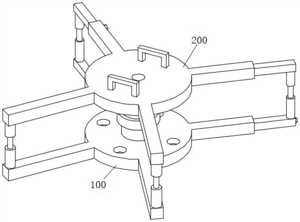
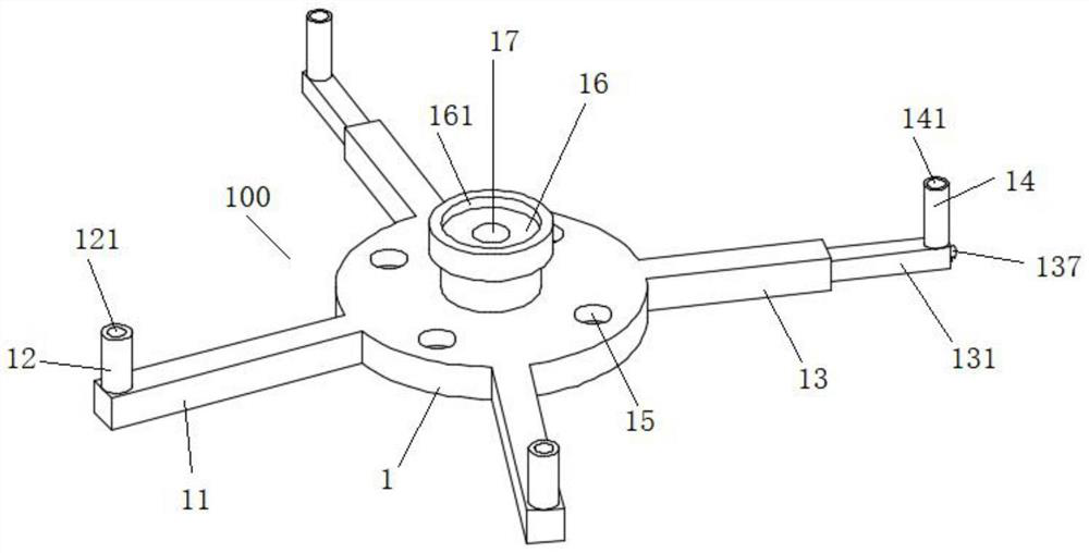
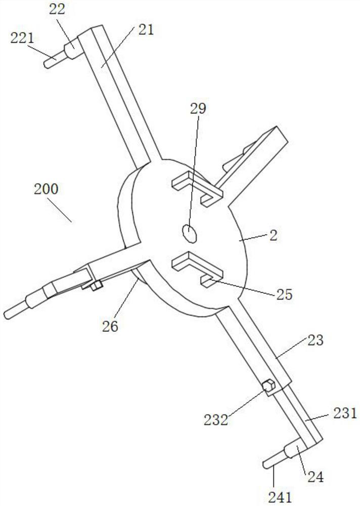
The invention discloses a vehicle-mounted spare tire storage rack, and relates to the technical field of automobile parts. The vehicle-mounted spare tire storage rack comprises a first support and a second support which are matched with each other, the first support comprises a first base plate, two first transverse rods and two first telescopic rods are arranged on the peripheral side of the first base plate, and first blocking rods A blocking the outer side of a tire are arranged at the ends of the first transverse rods; the end parts of the first telescopic rods are provided with first blocking rods B blocking the outer side of the tire; the second support comprises a second base plate, and two second transverse rods and two second telescopic rods are arranged on the peripheral side of the second base plate; second blocking rods A blocking the outer side of the tire is arranged at the end parts of the second cross rods, and second blocking rods B blocking the outer side of the tire are arranged at the end parts of the second telescopic rods; a first threaded through hole and a second threaded through hole are formed in the first base plate and the second base plate respectively; and the first support and the second support are connected through a screw rod. The first telescopic rods and the second telescopic rods are arranged on the first support and the second support correspondingly, so that the storage support assembly is suitable for storing various tires with different diameters.

Description

technical field [0001] The invention belongs to the technical field of automobile parts, in particular to a storage rack for a vehicle spare tire. Background technique [0002] In the related art, the spare tire support is a cross-shaped support structure, and the spare tire is placed on the cross-shaped support structure. The product quality of the spare tire mounting mechanism with this structure is often difficult to guarantee, especially the main struts, auxiliary struts and support plates of the spare tire bracket often have excessive contact with the rim during the process of compressing the spare tire, causing the rim to be squeezed and damaged. damage problem. [0003] Secondly, installing the spare tire through the spare tire bracket also has potential risks caused by uneven stress on the spare tire. Not only that, the versatility of the traditional spare tire mounting mechanism is poor, and there are fewer tire models that can be matched by a spare tire rack; the...

Claims


Application Information

Patent Timeline
Patent Type & Authority Applications(China)
IPC IPC(8): B62D43/00
CPCB62D43/00
Inventor 孙健
Owner 安徽正特机电科技有限公司
Learn More