Synchronous double-direct-acting driving energy-adjustable continuous winged unmanned aerial vehicle

A continuous belt, unmanned aerial vehicle technology, applied in helicopters, unmanned aerial vehicles, fuselage and other directions, can solve the problem of inability to achieve vertical take-off and landing and hovering in the air, restricting the popular application of flapping-wing aircraft, and the overall situation of flapping-wing aircraft. Low efficiency and other problems, to achieve the effect of simple structure, low production cost and good mobility

Pending Publication Date: 2022-01-07
GLOBAL INST OF SOFTWARE TECH
View PDF0 Cites 0 Cited by
  • Summary
  • Abstract
  • Description
  • Claims
  • Application Information

AI Technical Summary

Problems solved by technology

The main reason for the overall low efficiency of flapping wing aircraft is that most of the current research simply imitates the shape and flapping motion of the wings of birds or insects, but it is difficult to realize the use of the wing's own posture and structure in the process of flapping wings of flying creatures. The change of air resistance reduces air resistance and generates unsteady aerodynamic force, and the resulting low aerodynamic efficiency seriously restricts the popularization and application of flapping-wing aircraft
At the same time, most of the current flapping-wing aircraft cannot achieve vertical take-off and landing and hovering in the air, and their flexibility and maneuverability are not good enough

Method used


Image

  • Synchronous double-direct-acting driving energy-adjustable continuous winged unmanned aerial vehicle
  • Synchronous double-direct-acting driving energy-adjustable continuous winged unmanned aerial vehicle
  • Synchronous double-direct-acting driving energy-adjustable continuous winged unmanned aerial vehicle

Examples


Embodiment 1

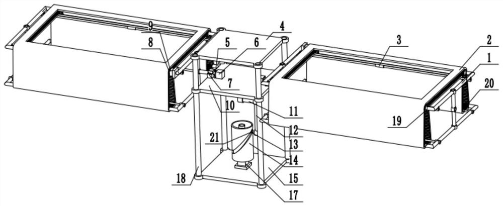
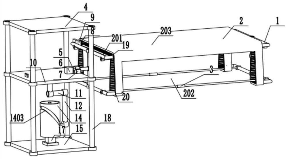
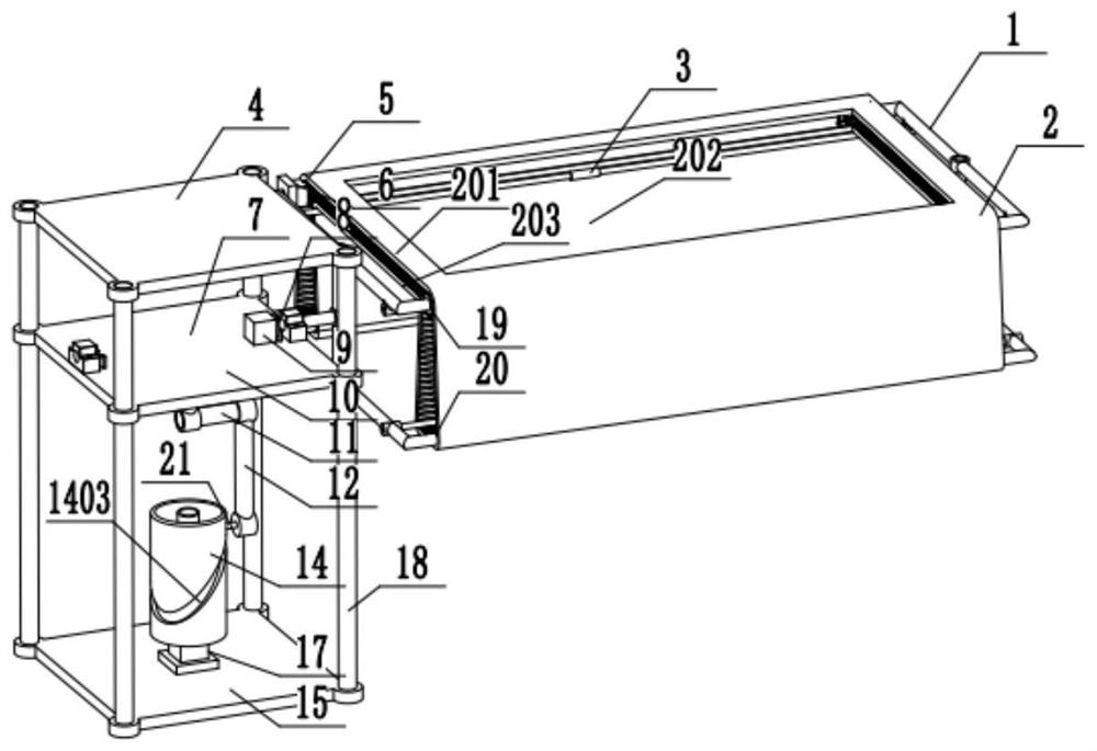
[0034] Example 1: Combining figure 1 , figure 2 , image 3 , Figure 4 , Figure 5 , Image 6 , Figure 7 , Figure 8 , Figure 9 with Figure 10 , a high-voltage wire inspection drone that uses synchronous double direct drive energy-adjustable continuous winged drones. Including belt wings, fuselage top plate 4, first reducer 5, stepper motor 6, connector 7, second reducer 8, drive motor 9, transmission mechanism, fuselage bottom plate 15, third reducer 16, motor 17 And the slideway 18, the fuselage roof 4 is symmetrically installed and fixed with four vertical slideways 18, the two connecting parts 7 are fixedly connected to the push rod 10 respectively, and the two belt wings are respectively connected to the two connecting parts 7 and can be relatively rotated, the wing includes a winged frame 1, and a continuous soft belt 2 sleeved on the winged frame 1, the winged frame 1 is also provided with a driving motor 9 and a second speed reducer 8, the driving motor 9...

Embodiment 2

[0035] Example 2: Combining figure 1 , figure 2 , image 3 , Figure 4 , Figure 5 , Image 6 , Figure 7 , Figure 8 , Figure 9 with Figure 10 , a high-rise building fire-fighting drone that adopts synchronous double direct drive energy-adjustable continuous winged drone. Including belt wings, fuselage top plate 4, first reducer 5, stepper motor 6, connector 7, second reducer 8, drive motor 9, transmission mechanism, fuselage bottom plate 15, third reducer 16, motor 17 And the slideway 18, the fuselage roof 4 is symmetrically installed and fixed with four vertical slideways 18, the two connecting parts 7 are fixedly connected to the push rod 10 respectively, and the two belt wings are respectively connected to the two connecting parts 7 and can be relatively rotated, the wing includes a winged frame 1, and a continuous soft belt 2 sleeved on the winged frame 1, the winged frame 1 is also provided with a driving motor 9 and a second speed reducer 8, the driving mot...


PUM


Abstract

The invention relates to a synchronous double-direct-acting driving energy-adjustable continuous belt wing unmanned aerial vehicle. Four slideways in the vertical direction are symmetrically and fixedly installed on the periphery of the fuselage top plate, the two belt wings can slide on the slideways, meanwhile, the two belt wings are connected to the two connecting pieces respectively and can rotate relatively, each belt wing comprises a belt wing frame and a soft belt installed on the belt wing frame, and a belt wheel, a tensioning wheel and a driving motor are further arranged in the belt wing frame, and used for switching between the working state and the reset sate of the belt wings, the transmission mechanism is connected to the two connecting pieces, and a motor arranged on the bottom plate of the fuselage drives the transmission mechanism to move after being decelerated through a third speed reducer so that the two connecting pieces can synchronously slide up and down. The two stepping motors arranged on the two connecting pieces correspondingly drive the two belt wings to rotate after being decelerated through the two first speed reducers.

Description

technical field [0001] The invention relates to the field of movable wing aircraft and flying robots, in particular to a synchronous double direct drive energy-adjustable continuous winged unmanned aerial vehicle. Background technique [0002] There are three flight types of aircraft flying: fixed wing, rotary wing and flapping wing. Among them, flapping wing flight is the flying mode adopted by flying creatures in nature. It mainly uses the up and down flapping of the wings to generate lift and thrust at the same time. , hovering and propulsion functions are based on one body, and at the same time have strong maneuverability and flexibility, and are more suitable for flying around obstacles. For small-sized and low-speed aircraft flying under low Reynolds numbers, the unsteady lift generated by the flapping wing is much greater than the constant lift of the fixed wing; from the perspective of thrust, the propulsion efficiency of the flapping wing is higher than that of the ...

Claims


Application Information

Patent Timeline
Patent Type & Authority Applications(China)
IPC IPC(8): B64C33/00B64C33/02B64C21/02B64C21/08B64C1/00
CPCB64C33/00B64C33/025B64C21/02B64C21/08B64C1/00B64C2001/0072B64U2101/00
Inventor 邱明苏朗杜相锋曹婷婷许建周旻廖振强
Owner GLOBAL INST OF SOFTWARE TECH
Why Eureka
Try Eureka