High-speed backboard connector

A high-speed backplane and connector technology, applied in the direction of connecting parts, such as protective grounding/shielding devices, fixed/insulating contact members, etc., can solve problems such as damage to the hook, poor impedance consistency, signal attenuation, etc., to reduce the impact of crosstalk, wall thickness The effect of reducing demand and shortening the return path

Pending Publication Date: 2022-01-07
SICHUAN HUAFENG ENTERPRISE GRP
View PDF0 Cites 1 Cited by
  • Summary
  • Abstract
  • Description
  • Claims
  • Application Information

AI Technical Summary

Problems solved by technology

The occupation of space makes the wall thickness of the female end base thinner and lower, and the strength is lower and lower, which reduces the reliability of the connector
In addition, the signal module mostly adopts a single-reed structure with one side touching the wall, and only uses a metal enclosure to fix the signal module. The fixation is not firm, and it is easy to cause the signal module to tilt relative to the female end base, which makes the connection reliability of the single-reed structure become worse
In addition, the hook of the signal module and the window of the female end base need to be assembled with interference. When the interference is large, it is easy to cause the hook to rub against the window, damage the hook, and produce plastic chips, resulting in insufficient holding force of the female end base. When the amount of interference is small, it directly leads to insufficient holding force of the base of the female end
[0004] In high-speed differential signal transmission, the impedance fluctuates greatly, which has an adverse effect on parameters such as insertion loss and return loss, resulting in signal attenuation. Therefore, matching impedance is the premise of high-speed backplane connector design
When the male base of the existing high-speed backplane connector is mated with the female base, the impedance of the contact area fluctuates greatly, and the impedance consistency is poor, which has an adverse effect on parameters such as insertion loss and return loss, resulting in signal attenuation

Method used


Image

  • High-speed backboard connector
  • High-speed backboard connector
  • High-speed backboard connector

Examples


Embodiment Construction

[0060] In order to make the technical problems solved by the present invention, the technical solutions adopted and the technical effects achieved clearer, the technical solutions of the embodiments of the present invention will be further described in detail below in conjunction with the accompanying drawings. Obviously, the described embodiments are only the technical solutions of the present invention. Some, but not all, embodiments. Based on the embodiments of the present invention, all other embodiments obtained by those skilled in the art without creative efforts fall within the protection scope of the present invention.

[0061] In the description of the present invention, it should be noted that the terms "center", "upper", "lower", "left", "right", "vertical", "horizontal", "inner", "outer" etc. The indicated orientation or positional relationship is based on the orientation or positional relationship shown in the drawings, and is only for the convenience of describin...


PUM


Abstract

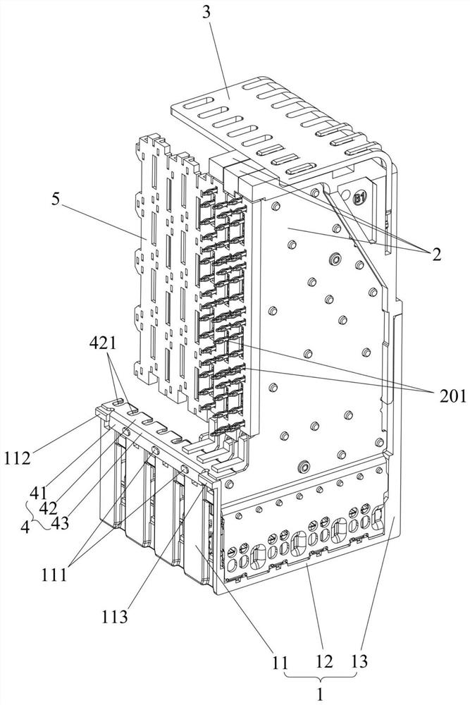
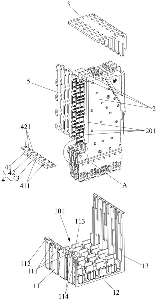
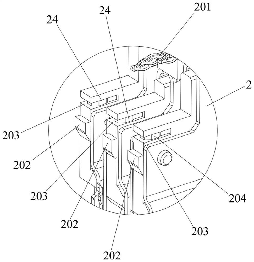
The invention relates to the field of connectors, and discloses a high-speed backboard connector. The high-speed backboard connector comprises a female end base, signal modules and a grounding piece, a containing groove is formed in the female end base, the signal modules are inserted into the containing groove side by side, the signal modules comprise the first signal module and the second signal module which are arranged adjacently, the first signal module comprises a first convex hull shielding piece and a first elastic piece shielding piece, the second signal module comprises a second convex hull shielding piece, the grounding piece is arranged between the female end base and the first signal module, and the grounding piece is in lap joint with the first convex hull shielding piece, the first elastic piece shielding piece and the second convex hull shielding piece at the same time to form a surrounding type shielding structure so as to achieve the purposes of shortening a backflow path and optimizing crosstalk. Especially for a signal module which is located at the edge of the female end base and cannot achieve effective shielding, surrounding type shielding of the signal module is achieved, the shielding effect is good, the backflow path is short, and the crosstalk influence of differential signal transmission is reduced.

Description

technical field [0001] The invention relates to the field of connectors, in particular to a high-speed backplane connector. Background technique [0002] High-speed backplane connectors usually design shielding pins on both sides of each group of signal modules to overlap with ground shrapnel to form an enveloping shield, shorten the return path, and optimize the crosstalk effect of differential signal transmission. The signal module at the edge cannot be equipped with ground shrapnel and shielding pins. Therefore, the signal module cannot achieve effective shielding, the return path is long, and the crosstalk phenomenon is relatively serious. The existing solution is: secondary injection molding of conductive plastic into the female end base of the high-speed backplane connector, and realize overlapping with the convex shell shielding parts of the two adjacent signal modules, so as to achieve the purpose of optimizing crosstalk. However, in this way, due to the influence o...

Claims


Application Information

Patent Timeline
Patent Type & Authority Applications(China)
IPC IPC(8): H01R13/648H01R13/40
CPCH01R13/648H01R13/40
Inventor 赵鹏尹继何洪
Owner SICHUAN HUAFENG ENTERPRISE GRP
Why Eureka
Try Eureka