Self-locking puller for zipper and zipper

A self-locking and zipper technology, applied in applications, sliding fastener components, fasteners, etc., can solve problems such as stiff, thin sliders, clumsy, and eye-catching

Pending Publication Date: 2022-01-11
KEE (GUANGDONG) GARMENT ACCESSORIES LTD
View PDF3 Cites 2 Cited by
  • Summary
  • Abstract
  • Description
  • Claims
  • Application Information

AI Technical Summary

Problems solved by technology

Although the thin slider can save the setting of the pull nose, so that the overall appearance is flat, but the operation part is arranged abruptly in front of the thin slider, which is particularl

Method used


Image

  • Self-locking puller for zipper and zipper
  • Self-locking puller for zipper and zipper
  • Self-locking puller for zipper and zipper

Examples


Embodiment approach 1

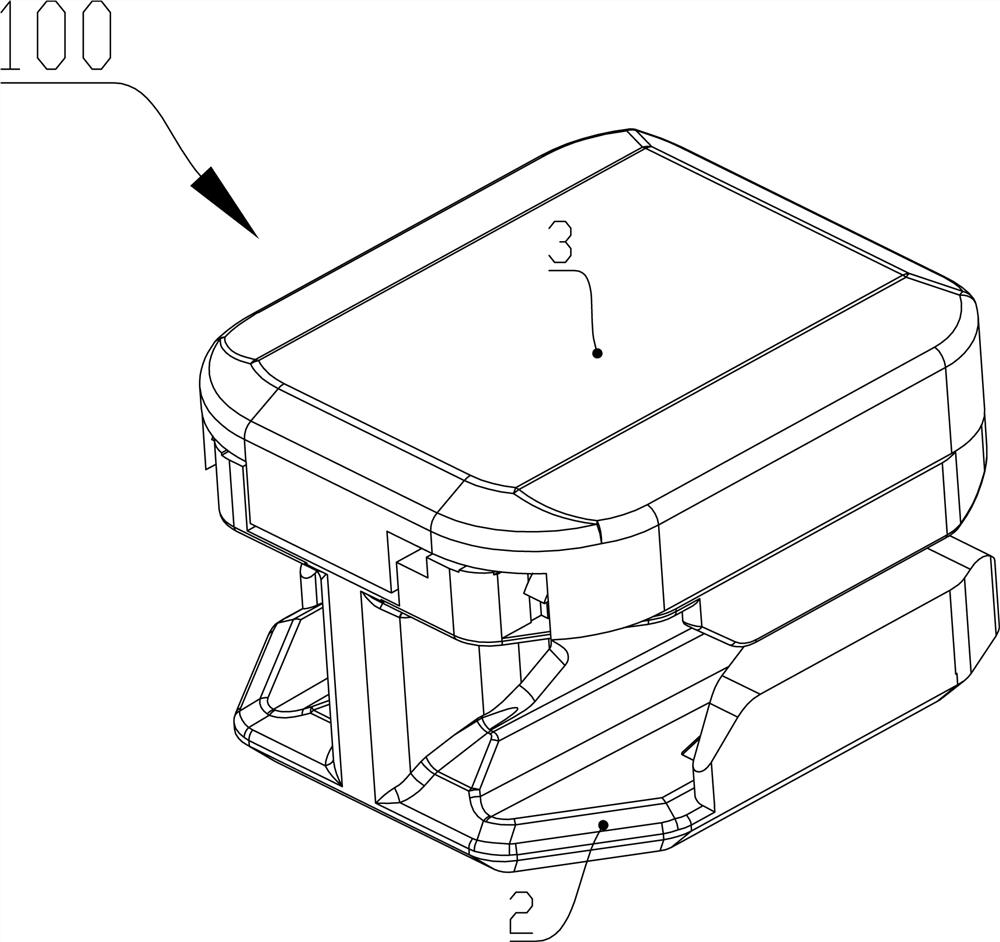
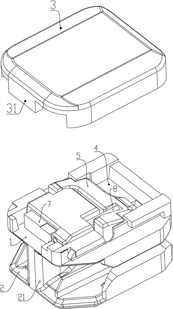
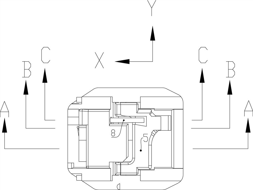
[0059] Such as Figure 1 to Figure 11 As shown, the present invention also proposes a slide fastener (not shown in the figure), including a chain belt and a self-locking slider 100 , and the self-locking slider 100 is slidably arranged on the chain belt. The self-locking slider 100 includes a first wing plate 1 and a second wing plate 2 separated up and down, and a chain element channel 22 is formed between them; an outer cover 3 is arranged on the first wing plate 1 , a storage space 4 is formed between the outer cover 3 and the first wing plate 1; it also includes a locking piece 5 arranged on the storage space 4, the locking piece 5 includes a support portion 52 and can be wound around The support part 52 is swingably inserted into the claw part 51 in the chain element passage 22; it also includes a first elastic body 8 arranged in the storage space 4, and the first elastic body 8 can act on the On the locking part 5, the claw portion 51 is inserted into the chain element ...

Embodiment approach 2

[0068] Such as Figure 12 to Figure 19 As shown, the self-locking slider 100a in Embodiment 2 has a similar structure to the self-locking slider 100 in Embodiment 1. The main differences between them will be introduced in detail below. Other features of the self-locking slider 100a The structure can be understood with reference to the relevant drawings and the above description of the self-locking slider 100 .

[0069] The locking member 5a includes a transverse connecting rod 54a, a pair of support parts 52a are located at the left and right ends of the transverse connecting rod 54a, and the first force receiving part 53a, the second force receiving part 55a, and the claw part 51a are arranged on the transverse connecting rod 54a. On the connecting rod 54a. Viewed laterally, the support portion 52a is located between the first force-receiving portion 53a and the claw portion 51a. A pair of wing plate pits 12a are arranged on the first wing plate 1a along the lateral directi...

Embodiment approach 3

[0072] Such as Figure 20 ~ Figure 26 As shown, the self-locking slider 100b in Embodiment 3 has a similar structure to the self-locking slider 100 in Embodiment 1. The main differences between them will be introduced in detail below. Other features of the self-locking slider 100b The structure can be understood with reference to the relevant drawings and the above description of the self-locking slider 100 .

[0073] The structures of the locking part and the first elastic body in this embodiment are different from those in the above two embodiments. The locking part and the first elastic body adopt an integral structure to form the spring piece 5b. The spring piece 5b includes a substrate portion 51b, a crest portion 52b and a claw portion 53b arranged in sequence. The uphill portion 521b, the gentle portion 522b, the downhill portion 523b extending obliquely downward relative to the gentle portion 522b, the claw portion 53b is connected to the downhill portion 523b, and th...


PUM


Abstract

A self-locking puller for the zipper comprises a first wing plate and a second wing plate which are separately arranged up and down, an outer cover is arranged on the first wing plate, and the outer cover is characterized in that a storage space is formed between the outer cover and the first wing plate; the zipper further comprises an upper locking piece arranged on the containing space, and the upper locking piece comprises a supporting part and a claw part capable of swinging around the supporting part to be inserted into the zipper tooth channel; the zipper further comprises a first elastic body arranged in the containing space, and the first elastic body can act on the upper locking piece to enable the claw part to be inserted into the zipper tooth channel; the storage space further comprises an unlocking part, and the unlocking part and the first elastic body are transversely arranged in the left-right direction when viewed in the longitudinal direction; the unlocking part can move longitudinally through the space provided by the containing space so that the unlocking part can have an unlocking position and a locking position; due to the fact that the containing space is formed between the outer cover and the first wing plate, enough installation and containing space is provided for internal components such as the upper locking piece and the first elastic body, and damage to the overall appearance of the self-locking pull head due to exposure of the internal components is reduced.

Description

technical field [0001] The invention relates to a slider with a self-locking mechanism, which is called a self-locking slider in the industry. The self-locking slider is positioned on a chain belt through the self-locking mechanism to maintain a stable zipper closure range. The invention also relates to a slide fastener using the self-locking slider. Background technique [0002] The applicant once proposed a utility model patent CN201721299705.3 on October 10, 2017, which disclosed a slider, including an upper cover, a lower cover and a slider connected between the upper cover and the lower cover. Intermediate connecting column. Wherein the upper cover plate is not provided with a pull nose for threading the pull ring, so that the overall appearance of the pull head is very simple and fashionable. However, during use, the slider is very easy to slide freely against the intention of use and change the closing range of the zipper, so it is necessary to add a self-locking me...

Claims


Application Information

Patent Timeline
IPC IPC(8): A44B19/30
CPCA44B19/303
Inventor 陈昌华
Owner KEE (GUANGDONG) GARMENT ACCESSORIES LTD
Why Eureka
Try Eureka