
Vibrating screen

A technology of vibrating screen and screen mesh, which is applied in the fields of filter screen, solid separation, chemical instruments and methods, etc., can solve the problems of waste of space materials, low work efficiency, and long time spent on screen mesh.

Active Publication Date: 2022-01-11
HENAN ZHONGYU DINGLI INTELLIGENT EQUIP CO LTD
View PDF5 Cites 0 Cited by
  • Summary
  • Abstract
  • Description
  • Claims
  • Application Information

AI Technical Summary

Problems solved by technology

[0002] Most of the vibrating screens in the prior art are fixedly connected to the screen box through densely arranged fastening bolts. When replacing the screen, it is necessary to manually enter the inside of the screen box to loosen the bolts for replacement. It costs more to replace the screen each time. long hours, low productivity
In addition, during production, in order to facilitate maintenance personnel to enter and exit to replace the screen, sufficient height needs to be left between each layer in the screen box, which wastes space and materials

Method used


Image

  • Vibrating screen
  • Vibrating screen
  • Vibrating screen

Examples


Embodiment Construction

[0020] The present invention will be described in detail below in conjunction with the embodiments.

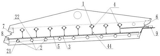
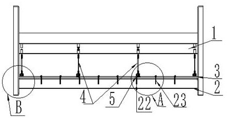
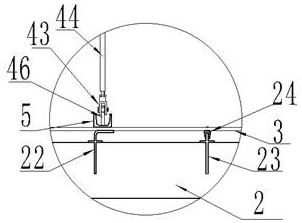
[0021] figure 1 It is a structural schematic diagram of the vibrating screen of the present invention, figure 2 for figure 1 left view of image 3 for figure 2 Enlarged view of A.

[0022] Such as figure 1 , 2 , 3, a vibrating screen of the present invention includes an upper sieve beam 1, a lower sieve beam 2, a screen 3 and a screen pressing mechanism 4. Figure 5 It is a structural schematic diagram of the connection between the screen pressing mechanism and the pressing rod, Figure 6 for Figure 5 left view of the , such as figure 2 , 5 , 6, the screen pressing mechanism 4 includes an upper connecting plate 41, a lower connecting plate 46, a normal thread Y-joint 42, a negative thread Y-joint 43 and a positive and negative thread screw 44. The upper connecting plate 41 is vertically fixed below the upper screen beam 1, and one end of the normal wire Y-shaped...


PUM


Abstract

The invention discloses a vibrating screen. The vibrating screen comprises an upper screen beam, a lower screen beam, a screen and a screen pressing mechanism, wherein the screen pressing mechanism comprises an upper connecting plate, a lower connecting plate, a right-hand Y joint, a left-hand Y joint and a right-hand and left-hand screw, and the upper connecting plate is vertically fixed below the upper screen beam; one end of the right-hand Y joint is vertically hinged to the upper connecting plate, and the other end is in threaded connection with the upper end of the right-hand and left-hand screw; one end of the left-hand Y joint is in threaded connection with the lower end of the left-hand and right-hand screw, and the other end of the left-hand Y joint is vertically hinged to the lower connecting plate; a pressing rod is fixed at the bottom of the lower connecting plate; when the end of the pressing rod abuts against a limiting block at the position of a discharging port of the vibrating screen, the right-hand and left-hand screw tends to be perpendicular to the screen; and a lower jacking block is fixed to the top of the lower screen beam, the screen is placed on the lower jacking block, and the lower jacking block and the pressing rod are used for pressing the screen up and down. In the use process of the vibrating screen, the screen pressing mechanism has a self-fastening effect on the screen, the right-hand and left-hand screw is pulled outwards to incline during disassembly, so that the screen is loosened and is convenient to disassemble, and time is saved and convenience is achieved.

Description

technical field [0001] The invention belongs to the technical field of material screening, in particular to a vibrating screen. Background technique [0002] Most of the vibrating screens in the prior art are fixedly connected to the screen box through densely arranged fastening bolts. When replacing the screen, it is necessary to manually enter the inside of the screen box to loosen the bolts for replacement. It costs more to replace the screen each time. For a long time, work efficiency is low. In addition, during production, in order to make it easier for maintenance personnel to enter and exit to replace the screen mesh, a sufficient height needs to be left between each layer in the screen box, which wastes space and materials. Contents of the invention [0003] The invention provides a vibrating screen mesh pressing device, which can quickly disassemble the screen mesh without manually entering the screen box for operation. [0004] Technical scheme of the present i...

Claims


Application Information

Patent Timeline
Patent Type & Authority Applications(China)
IPC IPC(8): B07B1/28B07B1/46B07B1/48
CPCB07B1/28B07B1/46B07B1/48
Inventor 刘文哲刘志君徐要忠
Owner HENAN ZHONGYU DINGLI INTELLIGENT EQUIP CO LTD
Learn More