
Automatic assembling mechanism for new energy automobile cooling connector positioning clamp

A new energy vehicle, automatic assembly technology, applied in the direction of workpiece clamping device, metal processing, metal processing equipment, etc., can solve the problems of machine jamming, low production efficiency, unstable quality, etc.

Pending Publication Date: 2022-01-11
CHONGQING SULIAN PLASTIC CO LTD
View PDF15 Cites 0 Cited by
  • Summary
  • Abstract
  • Description
  • Claims
  • Application Information

AI Technical Summary

Problems solved by technology

[0003] At present, one of the operation methods for producing new energy joints is: manual assembly operation, and the joints assembled by manual operation will have problems such as improper assembly of positioning cards, missing installation, etc., low production efficiency and unstable quality; the other is through automatic assembly machines. , the existing assembly machine is not accurate enough, causing the positioning card to be assembled and deformed, so that the defective rate of the new energy joint is too high, and the machine is often stuck. Therefore, the present invention proposes an automatic assembly mechanism for the positioning card of the new energy vehicle cooling joint. solve the above problems

Method used


Image

  • Automatic assembling mechanism for new energy automobile cooling connector positioning clamp
  • Automatic assembling mechanism for new energy automobile cooling connector positioning clamp
  • Automatic assembling mechanism for new energy automobile cooling connector positioning clamp

Examples


Embodiment Construction

[0025] The following will clearly and completely describe the technical solutions in the embodiments of the present invention with reference to the accompanying drawings in the embodiments of the present invention. Obviously, the described embodiments are only some of the embodiments of the present invention, not all of them. Based on the embodiments of the present invention, all other embodiments obtained by persons of ordinary skill in the art without making creative efforts belong to the protection scope of the present invention.

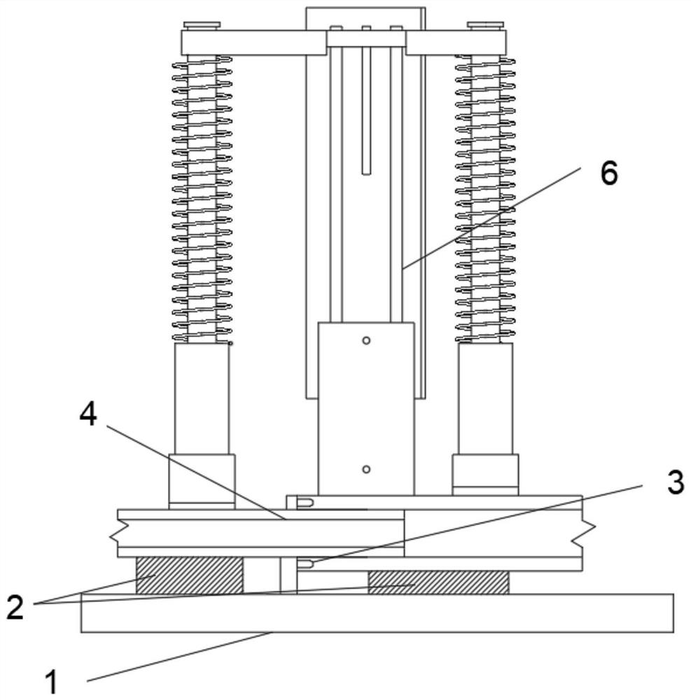
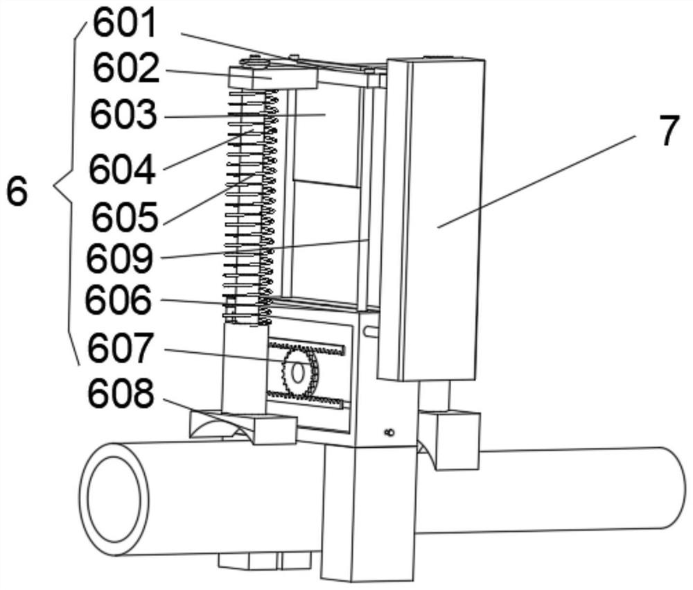
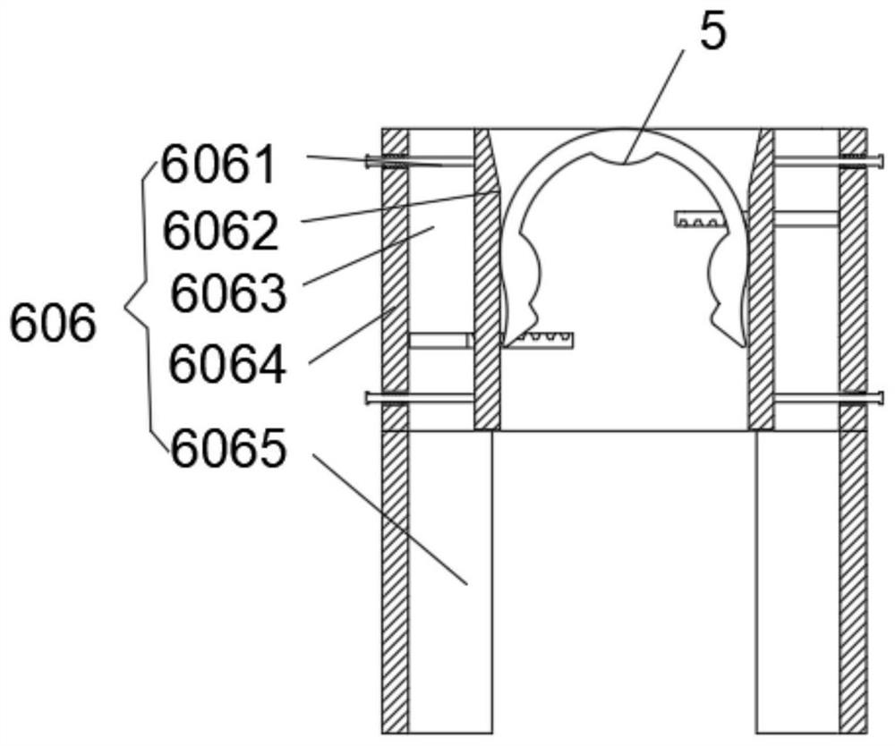
[0026] see Figure 1 to Figure 6 , the present invention provides a technical solution: a new energy vehicle cooling joint positioning card automatic assembly mechanism, including a base 1, two sets of supports 2 are set on the base 1, a positioning pin-3 is set in the middle of the base 1, and two sets of supports 2 are set The assembly mechanism 6 with auxiliary installation function, the positioning card 5 is arranged in the assembly mechanism...


PUM


Abstract

The invention relates to the technical field of automatic assembling mechanisms for positioning clamps, in particular to an automatic assembling mechanism for a new energy automobile cooling connector positioning clamp. The automatic assembling mechanism for the new energy automobile cooling connector positioning clamp comprises a base, wherein two sets of supports are arranged on the base; a first positioning pin is arranged in the middle of the base; an assembling mechanism with an auxiliary mounting function is arranged on the two sets of supports; a positioning clamp is arranged in the assembling mechanism; a carrying mechanism is arranged on one side of the assembling mechanism; and the positioning clamp is pressed into a rectangular hole to extrude side plates on the two sides, the side plates linearly retreat under the matching action of guide rods and vertical bearings, the side plates drive a rack through a first rod, the rack enables a first shaft to rotate through a gear, the rotation of the first shaft enables a coil spring in a coil spring box to deform, and the deformed coil spring generates reaction torque force, so that the two sets of side plates clamp the positioning clamp, and a pre-fixing effect is achieved on the positioning clamp.

Description

technical field [0001] The invention relates to the technical field of an automatic assembly mechanism for a positioning card, in particular to an automatic assembly mechanism for a positioning card for a cooling joint of a new energy vehicle. Background technique [0002] There is a part of the new energy joint product called a positioning card. Whether it is installed in place directly affects the reliability of the assembly of the new energy joint. Therefore, a positioning card assembly mechanism with a stable and reliable assembly structure is required. [0003] At present, one of the operation methods for producing new energy joints is: manual assembly operation, and the joints assembled by manual operation will have problems such as improper assembly of positioning cards, missing installation, etc., low production efficiency and unstable quality; the other is through automatic assembly machines. , the existing assembly machine is not accurate enough, causing the positi...

Claims


Application Information

Patent Timeline
Patent Type & Authority Applications(China)
IPC IPC(8): B23P19/04B25B11/02
CPCB23P19/04B25B11/02
Inventor 胡勇曹树林李旭阳徐明朱世鹏徐梓净杨毅韩宗俊
Owner CHONGQING SULIAN PLASTIC CO LTD
Learn More