Automatic glove strapping machine

An automatic strapping and glove technology, applied in the field of glove machines, can solve the problems of time-consuming and laborious, increased labor and production costs, and low efficiency of weaving gloves

Pending Publication Date: 2022-01-11
Zhejiang Baixiang Technology Co Ltd
View PDF1 Cites 5 Cited by
  • Summary
  • Abstract
  • Description
  • Claims
  • Application Information

AI Technical Summary

Problems solved by technology

[0002] Ordinary glove knitting machines generally have the technical problem of low finishing efficiency of knitting gloves. The Chinese patent with the authorized announcement number CN208362618U discloses a glove knitting machine and its finished product storage device, including the casing of the glove knitting machine and the discharge material on the casing. It also includes a storage basket located at the discharge port. There is a card slot on the casing, a hook is connected to the storage basket, and the end of the hook away from the storage basket is snapped into the card slot.
[0003] Although the above-mentioned patent has a storage basket at the outlet of the glove knitting machine, the knitted gloves are messy when they enter the storage basket, and they still need to be manually arranged into stacks one by one when collecting the gloves, and then It is time-consuming and labor-intensive to bind the stacks of gloves manually, which increases labor and production costs. The industry urgently needs an automatic equipment that can automatically bind the stacks of gloves with rubber bands.

Method used


Image

  • Automatic glove strapping machine
  • Automatic glove strapping machine
  • Automatic glove strapping machine

Examples


Embodiment Construction

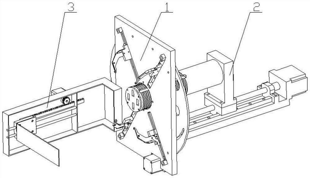
[0045] refer to Figure 1 to Figure 14 , this embodiment is used to install on the glove machine frame corresponding to the conveying device 5 receiving the glove stack 6, which includes a rubber band connecting and binding device 1, a rubber band placing device 2 and a glove pushing device 3;

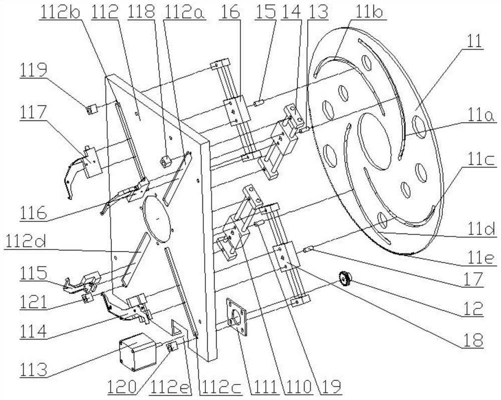
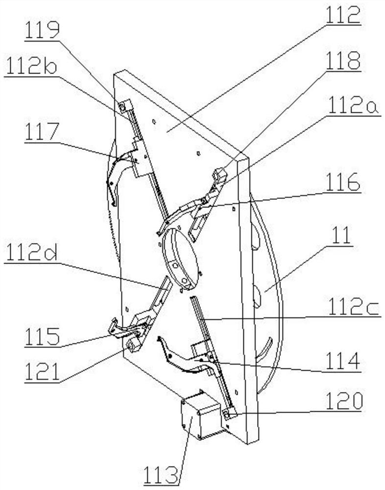
[0046] The rubber band connecting and binding device 1 is mainly composed of a sliding seat 112 which is vertically arranged and has a through hole and at least four hooking wire components with hook heads 41a. In this embodiment, there are four hooking wire components. Divided into the lower right hook assembly 114, the lower left hook assembly 115, the upper right hook assembly 116 and the upper left hook assembly 117, the sliding seat 112 is provided with the first chute 112a distributed in a divergent shape with the through hole as the center , the second chute 112b, the third chute 112c and the fourth chute 112d, the upper right hook line assembly 116, the upper left hook line ass...


PUM


Abstract

The invention discloses an automatic glove strapping machine, relates to the technical field of glove machines, and solves the problem about automatic rubber band strapping of stacked glove stacks. The machine comprises a rubber band receiving and strapping device, a rubber band placing device and a glove pushing device, the rubber band receiving and strapping device mainly comprises a sliding seat and a plurality of line hooking assemblies, the sliding seat is vertically arranged and is provided with a through hole, the line hooking assemblies are provided with hook heads, sliding grooves distributed in a divergent mode with the through hole as the center are formed in the sliding seat, the line hooking assemblies are driven to be installed in the sliding grooves in a reciprocating sliding mode, and the hook heads are located at the ends, facing the through hole, of the line hooking assemblies. Rubber band grooves and radial through grooves are formed in the circumference and the radial direction of a rubber band roller correspondingly, so that the rubber band placing device and the line hooking assemblies can be matched to hook rubber bands conveniently, rubber band releasing strips are arranged in the line hooking assemblies, the rubber bands can be released conveniently after the glove stacks enter the rubber bands pulled into square shapes, the labor force can be reduced, and the automation degree of strapping the glove stacks can be improved.

Description

technical field [0001] The invention relates to the technical field of glove machines, in particular to an automatic glove binding machine. Background technique [0002] Ordinary glove knitting machines generally have the technical problem of low finishing efficiency of knitting gloves. The Chinese patent with the authorized announcement number CN208362618U discloses a glove knitting machine and its finished product storage device, including the casing of the glove knitting machine and the discharge material on the casing. The opening also includes a storage basket located at the discharge port, a slot is provided on the casing, a hook is connected to the storage basket, and the end of the hook away from the storage basket is snapped into the slot. [0003] Although the above-mentioned patent has a storage basket at the outlet of the glove knitting machine, the knitted gloves are messy when they enter the storage basket, and they still need to be manually arranged into stack...

Claims


Application Information

Patent Timeline
Patent Type & Authority Applications(China)
IPC IPC(8): B65B13/18B65B25/20
CPCB65B13/18B65B25/20
Inventor 陈百祥冯建明
Owner Zhejiang Baixiang Technology Co Ltd
Why Eureka
Try Eureka