A camera device for industrial visual inspection

A technology of visual inspection and photographic device, applied in the field of visual inspection, can solve the problems of image capture of objects, affect inspection quality, limitation of photographic surface, etc., and achieve the effect of enhancing visual inspection quality, improving inspection quality, and improving inspection range.

Active Publication Date: 2022-03-22
深圳宇骏视觉智能科技有限公司
View PDF0 Cites 0 Cited by
  • Summary
  • Abstract
  • Description
  • Claims
  • Application Information

AI Technical Summary

Problems solved by technology

[0002] With its absolute advantages of high efficiency, high accuracy and low cost, machine vision has brought technological innovation to many traditional industries. Visual inspection technology is a subject involving artificial intelligence, neurobiology, psychophysics, computer science, image processing, etc. Interdisciplinary subjects in many fields such as , pattern recognition, etc. are an indispensable part of the intelligent manufacturing industry. The existing photographic device for visual inspection, but because the workpiece to be inspected is relatively fixed, the photographic surface is too limited, resulting in the machine's detection of the object. The capture of the image is affected, affecting the detection quality

Method used


Image

  • A camera device for industrial visual inspection
  • A camera device for industrial visual inspection
  • A camera device for industrial visual inspection

Examples


Embodiment 1

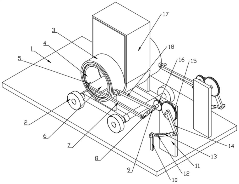
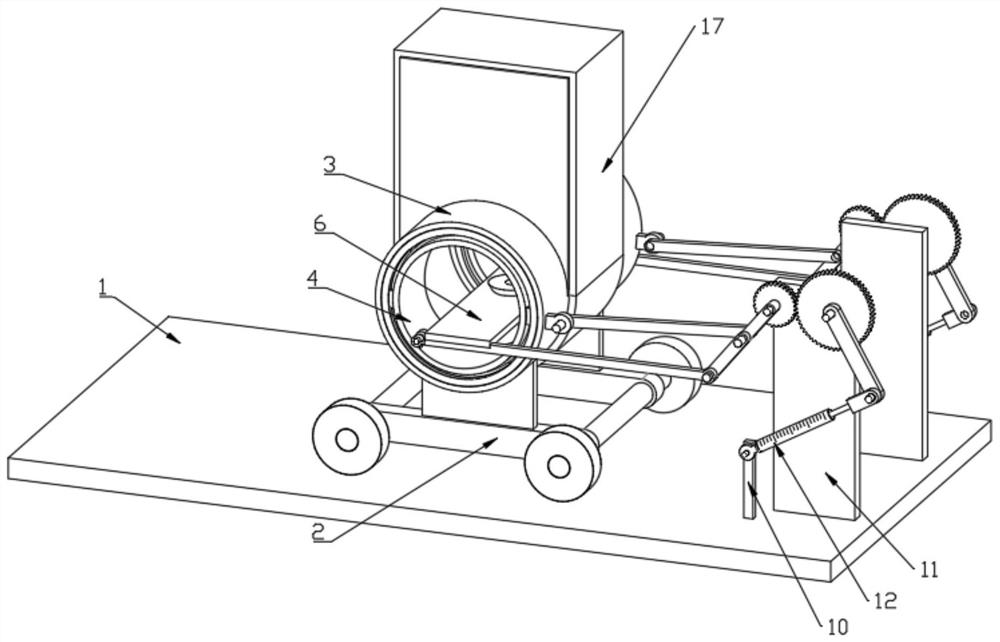
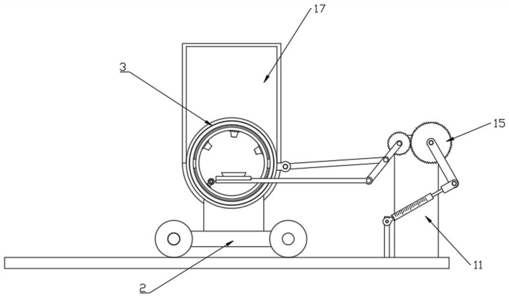
[0034]Embodiment 1, as a mode of the first drive mechanism, the first drive mechanism includes a first gear 15 and a first electric telescopic rod 12, the first gear 15 is rotatably installed on the upper part of the fixed plate 11, the first gear 15 and the first Two gears 16 meshing transmission, the first gear 15 is fixedly installed with the fourth connecting rod 14, the first electric telescopic rod 12 is installed on the bottom plate 1 through the rotation of the fixed rod 10, the first electric telescopic rod 12 is connected with the fourth through the telescopic rod One end of the rod 14 away from the first gear 15 is rotatably mounted.

[0035] By driving the first electric telescopic rod 12 to work, due to the length change of the first electric telescopic rod 12, the fourth connecting rod 14 and the first gear 15 can be further driven to rotate, and due to the meshing effect between the second gear 16 and the first gear 15 , can further drive the second gear 16 and ...

Embodiment 2

[0038] Embodiment 2, as another way of the first drive mechanism, further, the second drive mechanism for rotating the second gear 16 is connected to the fixed plate 11, and the second drive mechanism includes a second drive mechanism fixed on the fixed plate 11. The fixed part 31 on one side, the motor 32 is fixedly installed on the fixed part 31, the output shaft of the motor 32 passes through the fixed plate 11 and is connected with the first gear 15 in rotation, the outer wall of the output shaft of the motor 32 is fixed with a pointer 34, the pointer 34 A scale plate 33 is installed on the side wall of the fixed plate 11 where it is located.

[0039] The first gear 15 is driven by the motor 32 to rotate in a feeding manner, which is convenient for locking after rotation. At the same time, due to the cooperation of the pointer 34 and the dial 33, it is convenient to display the specific value of the rotation position of the first gear 15. Use the corresponding value One-to...


PUM


Abstract

The invention discloses a photographing device for industrial visual inspection, which comprises a bottom plate, two fixed sleeves are arranged on the upper surface of the bottom plate through a moving frame, and inside the two fixed sleeves are provided with a device for changing the placement position of workpieces. Two sets of support and deflection mechanisms; each set of support and deflection mechanisms includes a rotating sleeve and a fixed plate, the rotating sleeve is rotatably mounted on the inner wall of the fixed sleeve, the fixed plate is fixedly mounted on the upper surface of the bottom plate, and the upper part of the fixed plate A second gear is rotatably installed, and the support plate is arranged inside two rotatable sleeves, one of which is equipped with a camera for taking pictures of the workpiece in different directions. Through the setting of the support deflection mechanism, the invention can realize taking pictures of different positions of the workpiece, so that the image of the object can be captured more comprehensively and the detection quality can be improved.

Description

technical field [0001] The invention relates to the technical field of visual inspection, in particular to a photographic device for industrial visual inspection. Background technique [0002] With its absolute advantages of high efficiency, high accuracy and low cost, machine vision has brought technological innovation to many traditional industries. Visual inspection technology is a subject involving artificial intelligence, neurobiology, psychophysics, computer science, image processing, etc. Interdisciplinary subjects in many fields, such as , pattern recognition, etc., are an indispensable part of the intelligent manufacturing industry. The existing photographic device for visual inspection, however, due to the relatively fixed workpiece to be inspected, the photographic surface is too limited, causing the machine to accurately detect the object. Image capture is affected, affecting detection quality. Contents of the invention [0003] The object of the present inven...

Claims


Application Information

Patent Timeline
Patent Type & Authority Patents(China)
IPC IPC(8): H04N5/232H04N5/225F16M11/10F16M11/18
CPCF16M11/10F16M11/18H04N23/50H04N23/69H04N23/695
Inventor 张啸宇刘骏
Owner 深圳宇骏视觉智能科技有限公司
Why Eureka
Try Eureka