
Solid mineral exploration combined geological compass

A combined, mineral technology, applied in the direction of compass, measuring device, surveying and navigation, etc., can solve the problems of incomplete and accurate measurement data, inability to protect the compass, and reduce the service life of the device, so as to achieve accurate and practical measurement The effect of high performance and convenient operation

Pending Publication Date: 2022-01-14
山东省地质矿产勘查开发局第七地质大队
View PDF0 Cites 0 Cited by
  • Summary
  • Abstract
  • Description
  • Claims
  • Application Information

AI Technical Summary

Problems solved by technology

[0003] The traditional geological compass used for mineral exploration generally has relatively simple functions and structures. When it is actually used, it cannot measure the desired data comprehensively and accurately, and the traditional device cannot protect the compass well. When in use, the compass is easily damaged by environmental interference, which reduces the service life of the device

Method used


Image

  • Solid mineral exploration combined geological compass
  • Solid mineral exploration combined geological compass
  • Solid mineral exploration combined geological compass

Examples


Embodiment 1

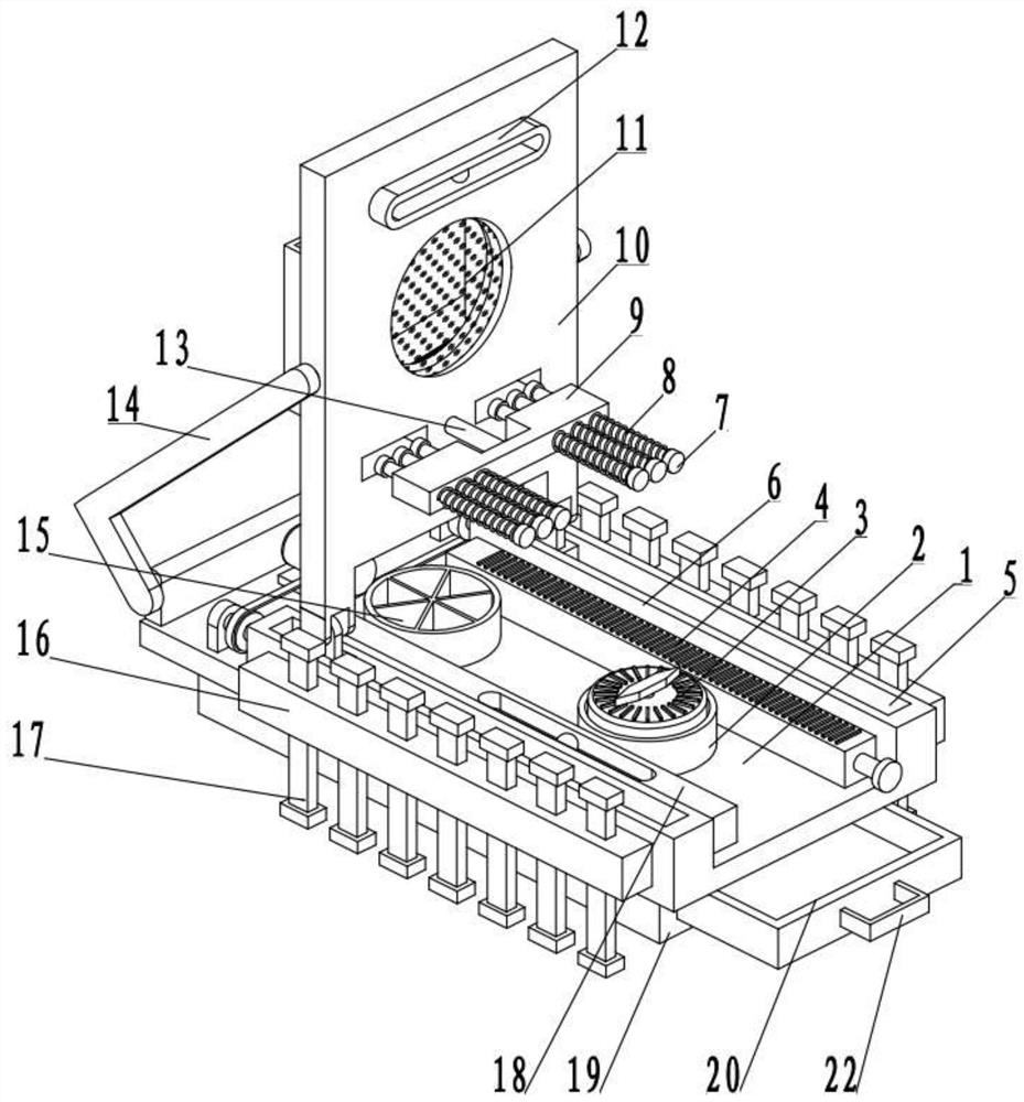
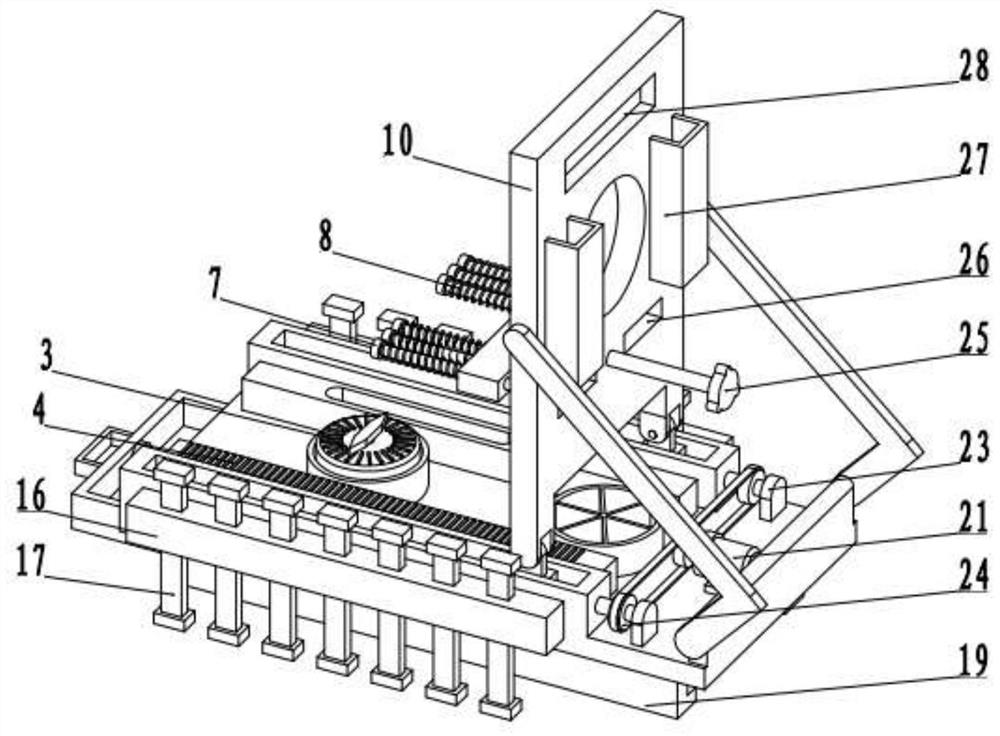
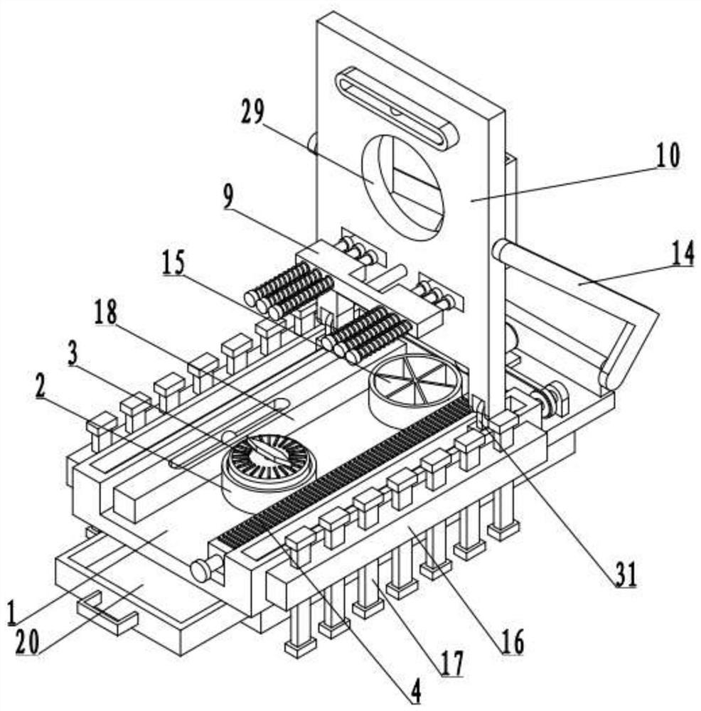
[0029] see Figure 1-6 , a combined geological compass for solid mineral exploration, including a base plate 1, and also includes:

[0030] The mounting rods 6 fixedly arranged on both sides of the bottom plate 1, and the mounting plate 10 is arranged on one side of the mounting rod 6;

[0031] The measuring mechanism arranged on the bottom plate 1 includes an installation groove 2, in which a compass member 3 is fixed by bolts, and the bottom plate 1 on one side of the installation groove 2 is fixedly connected to the storage groove 15, and the bottom plates on both sides of the storage groove 15 1, the measuring ruler 4 and the second spirit level 18 are respectively fixedly installed, the side wall of the installation rod 6 is fixedly connected to the positioning shell 16, and the positioning shell 16 is slid to pass through the supporting rod 17, and the positioning cavity 36 is opened in the positioning shell 16, and the positioning A positioning component 37 is provided...

Embodiment 2

[0035] see Figure 1-6 , the other content of this embodiment is the same as that of Embodiment 1, the difference is that: the positioning assembly 37 includes a telescopic tube 32 fixedly arranged on one side of the positioning chamber 36, and a telescopic member 33 is sleeved on the telescopic tube 32, and the telescopic tube 32 One side of the cylinder 32 is fixedly connected with the stop protrusion 34, and the side wall of the support rod 17 on the side of the stop protrusion 34 is provided with a positioning groove 35, and the telescopic member 33 can use a spring or elastic metal sheet with telescopic properties.

[0036] The telescoping assembly 38 includes a measuring column 7, which slides through and is arranged on the limit frame 9, and one side of the measuring column 7 is sleeved with an elastic member 8, and one side of the mounting column 13 is fixedly connected to the mounting handle 25, so that The above-mentioned elastic member 8 can use a spring with stretc...


PUM


Abstract

The invention discloses a solid mineral exploration combined geological compass, and relates to the technical field of mineral exploration. The solid mineral exploration combined geological compass comprises a bottom plate, and further comprises mounting rods arranged on two sides of the bottom plate, and a mounting plate is arranged on one side of each mounting rod. The solid mineral exploration combined geological compass further comprises a measuring mechanism arranged on the bottom plate, the measuring mechanism comprises a mounting groove, a compass piece is arranged in the mounting groove, a storage groove is fixedly connected to the bottom plate on one side of the mounting groove, a measuring scale and a second gradienter are arranged on the bottom plate on the two sides of the storage groove respectively, a positioning shell is fixedly connected to the side wall of each mounting rod, a supporting rod is arranged on each positioning shell in a sliding and penetrating mode, a positioning cavity is formed in each positioning shell, and a positioning assembly is arranged in each positioning cavity and used for supporting and adjusting the measuring mechanism to keep horizontal; and the solid mineral exploration combined geological compass further comprises adriving mechanism is arranged on one side of the mounting plate and used for adjusting the position of the mounting plate.

Description

technical field [0001] The invention relates to the technical field of mineral exploration, in particular to a combined geological compass for solid mineral exploration. Background technique [0002] The geological compass is an indispensable tool for field geological work; with it, you can determine the direction, the location of the observation point, measure the spatial position of any observation surface, and determine various structural elements of igneous rocks, ore bodies production, etc. [0003] The traditional geological compass used for mineral exploration generally has relatively simple functions and structures. When it is actually used, it cannot measure the desired data comprehensively and accurately, and the traditional device cannot protect the compass well. When in use, the compass is easily damaged by environmental interference, which reduces the service life of the device. Contents of the invention [0004] The invention provides a combined geological ...

Claims


Application Information

Patent Timeline
IPC IPC(8): G01C17/00
CPCG01C17/00
Inventor 冯爱平刘传朋李新凤冯广
Owner 山东省地质矿产勘查开发局第七地质大队
Learn More