
Thrust conversion mechanism

A technology of converting mechanism and thrust, applied in mechanical equipment, instruments, electrical and digital data processing, etc., can solve problems such as damage to the continuity of the picture

Pending Publication Date: 2022-01-18
COPAL CO LTD
View PDF1 Cites 0 Cited by
  • Summary
  • Abstract
  • Description
  • Claims
  • Application Information

AI Technical Summary

Problems solved by technology

If there is a gap between the ends of the two housings on which the monitors are installed, a gap will also be created between the ends of the two monitors, and the continuity of the screen will be impaired.

Method used


Image

  • Thrust conversion mechanism
  • Thrust conversion mechanism
  • Thrust conversion mechanism

Examples


Embodiment Construction

[0030] Hereinafter, an example of the thrust converting mechanism to which the present invention is applied will be described in detail with reference to the drawings. In addition, in the following description, the same reference numerals are used for the same or substantially the same configurations, elements, and the like, and overlapping descriptions are appropriately omitted.

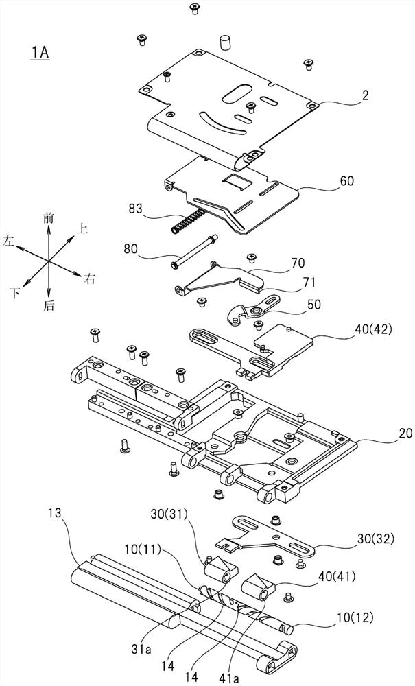
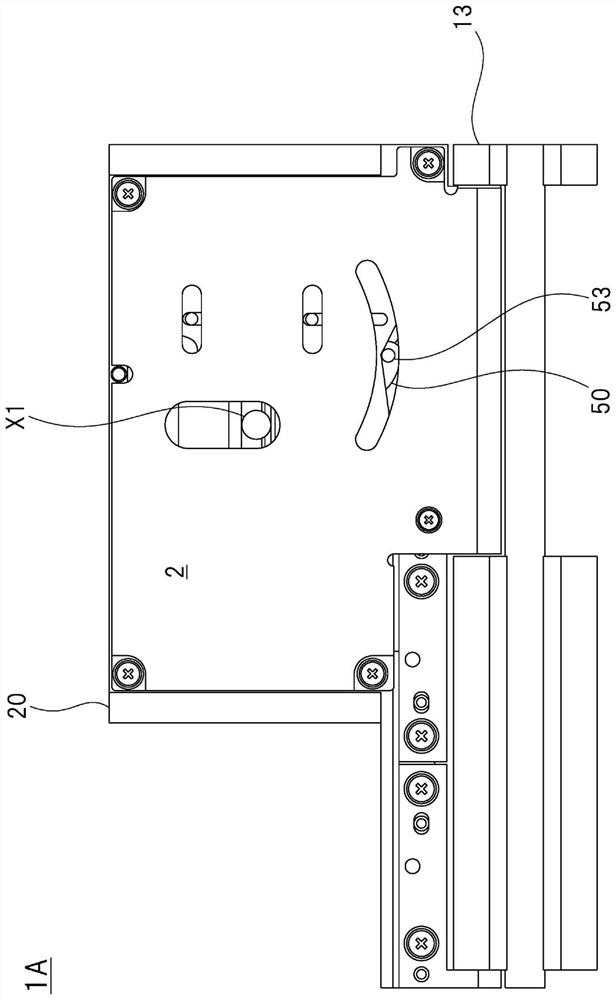
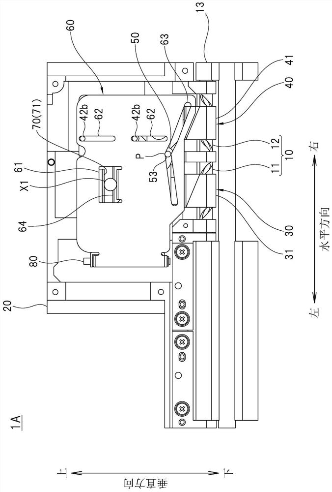
[0031] Such as figure 1 As shown, the thrust conversion mechanism 1A of this embodiment has a shaft 10, a housing 20, a first linear motion member 30, a second linear motion member 40, a rotary member 50, a drive member 60, and a buffer member 70. These constituent elements are as follows: Figure 2 ~ Figure 6 combined as shown. in addition, figure 2 It is a front view of the thrust converting mechanism 1A. In addition, in Figure 3 ~ Figure 6 In each of the drawings, in order to illustrate the internal structure of the thrust conversion mechanism 1A, some components are omitted. For example, ...


PUM


Abstract

The invention provides a thrust conversion mechanism. The conversion efficiency of the thrust conversion mechanism is improved. The thrust conversion mechanism is provided with: a shaft (10) having a pair of spiral engagement parts having opposite spiral directions; a housing (20) that is rotatable with respect to the shaft and supports a first linear motion member (30) and a second linear motion member (40) so as to be movable along the shaft; a rotating member (50) that rotates in accordance with the movement of the first linear motion member and the second linear motion member; a driving member (60) that moves in a direction intersecting the shaft in accordance with the rotation of the rotating member; and a buffer member (70) that comes into contact with the object to be moved from the opposite side to the driving member. The thrust conversion mechanism has a first state in which the driving member and the buffer member move in accordance with the movement of the driving member, and a second state in which the buffer member moves and the driving member does not move in accordance with the movement of the object to be moved.

Description

technical field [0001] The present invention relates to thrust conversion mechanisms. Background technique [0002] There are known converting mechanisms that convert rotary motion into linear motion, or convert linear motion into rotary motion. For example, a feed screw mechanism (refer to Patent Document 1) constituted by a threaded shaft with threads formed on its outer peripheral portion and a nut screwed with the threaded shaft is an example of the conversion mechanism. [0003] Patent Document 1: Japanese Publication No. 54-23979 [0004] In the feed screw mechanism, in order to increase the amount of movement of the nut while the rotation angle of the screw shaft is restricted, it is necessary to increase the lead of the screw. However, if the lead of the screw is increased, the load when the nut is moved increases, and thus a large driving force is required to rotate the threaded shaft. In addition, since the movement direction of the nut is limited to a linear di...

Claims


Application Information

Patent Timeline
Patent Type & Authority Applications(China)
IPC IPC(8): F16H25/12F16C11/04F16C11/10F16C11/12F16F15/067G06F1/16
CPCF16H25/122F16C11/04F16C11/10F16C11/12F16F15/067G06F1/1681
Inventor 柳沼大祐
Owner COPAL CO LTD
Learn More