Pipeline connecting structure

A connection structure and pipeline technology, applied in flange connection, sleeve/socket connection, pipe/pipe joint/pipe fitting, etc., can solve leakage, sealing surface is difficult to achieve the expected sealing effect, inconvenient to approach or shut down for maintenance, etc. problems, to achieve good sealing effect, make up for deviations, and reduce stiffness requirements

Pending Publication Date: 2022-01-18
CSSC POWER INST CO LTD
View PDF0 Cites 0 Cited by
  • Summary
  • Abstract
  • Description
  • Claims
  • Application Information

AI Technical Summary

Problems solved by technology

However, in actual use, due to factors such as machining accuracy and installation accuracy, this rigid connection method often makes it difficult for the sealing surface between the two components to achieve the expected sealing effect, and leakage often occurs, especially when the pressure inside the pipe is high. , or when the equipment is in a state of vibration, the leakage phenomenon is more frequent
In addition, for large mechanical equipment or high-speed operating equipment, it is not convenient to approach or shut down for maintenance

Method used


Image

  • Pipeline connecting structure
  • Pipeline connecting structure
  • Pipeline connecting structure

Examples


Embodiment Construction

[0027] In order to make the technical problems solved by the present invention, the technical solutions adopted and the technical effects achieved clearer, the technical solutions of the embodiments of the present invention will be further described in detail below in conjunction with the accompanying drawings. Obviously, the described embodiments are only the technical solutions of the present invention. Some, but not all, embodiments. Based on the embodiments of the present invention, all other embodiments obtained by those skilled in the art without creative efforts fall within the protection scope of the present invention.

[0028] In the description of the present invention, it should be noted that the terms "center", "upper", "lower", "left", "right", "vertical", "horizontal", "inner", "outer" etc. The indicated orientation or positional relationship is based on the orientation or positional relationship shown in the drawings, and is only for the convenience of describin...


PUM


Abstract

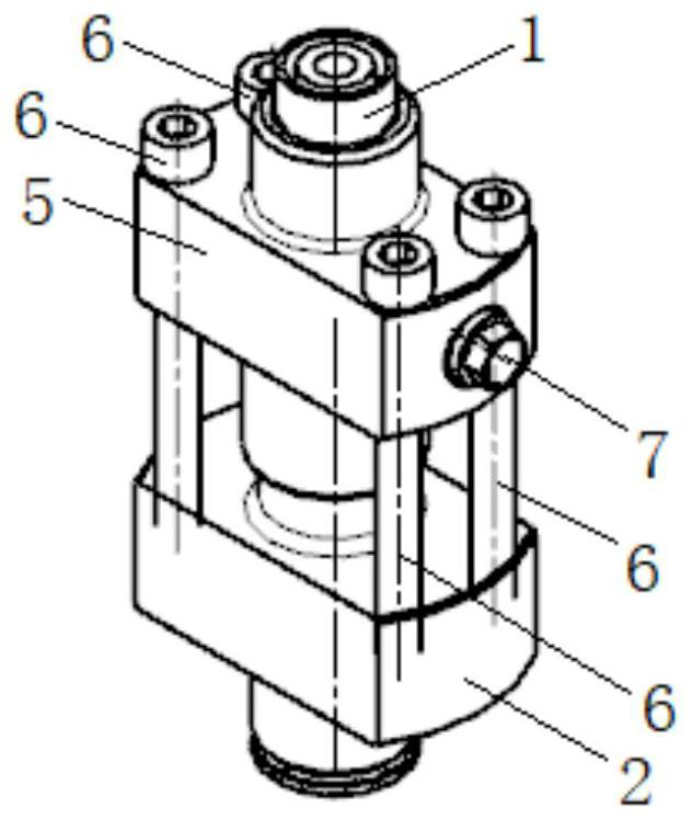
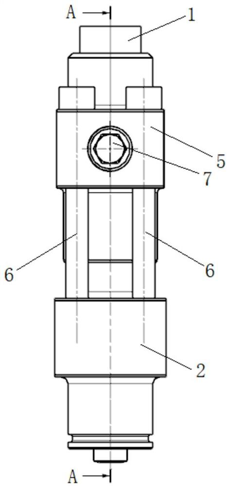
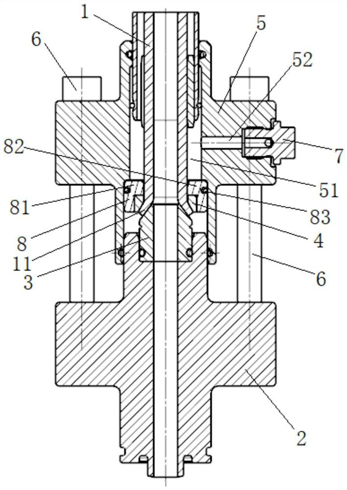
The invention relates to the technical field of pipeline sealing, and discloses a pipeline connecting structure. The pipeline connecting structure comprises a pipeline piece, a matching piece, a conical surface piece, a pressing piece, a connecting flange and a locking piece, wherein a flaring portion is arranged at the end, facing the matching piece, of the pipeline piece, the conical surface piece is coaxially arranged on the matching piece and is matched with the flaring portion, the matching surface of the conical surface piece and the flaring portion is a conical surface, the pressing piece is arranged on the peripheral side of the flaring portion in a sleeving mode so as to press the flaring portion on the conical surface piece, and the connecting flange is arranged on the peripheral sides of the pipeline piece and the pressing piece in a sleeving mode and is connected with the matching piece through the locking piece. According to the pipeline connecting structure, the rigidity requirement of the flaring portion is reduced, then deviation generated in the machining and assembling process is made up, it is ensured that the matching surface of the conical surface piece and the flaring portion is in an ideal connection state, the sealing effect is good, and the machining and assembling requirements are low.

Description

technical field [0001] The invention relates to the technical field of pipeline sealing, in particular to a pipeline connection structure. Background technique [0002] During the operation of the equipment, it is often necessary to transmit liquids such as high-pressure servo oil and fuel oil, and a relatively rigid connection method is often used between two components. However, in actual use, due to factors such as machining accuracy and installation accuracy, this rigid connection method often makes it difficult for the sealing surface between the two components to achieve the expected sealing effect, and leakage often occurs, especially when the pressure inside the pipe is high. , or when the equipment is in a vibrating state, the leakage phenomenon is more frequent. In addition, for large mechanical equipment or equipment operating at high speed, it is not convenient to approach or shut down for maintenance. Contents of the invention [0003] Based on the above pro...

Claims


Application Information

Patent Timeline
Patent Type & Authority Applications(China)
IPC IPC(8): F16L23/024F16L23/032F16L23/16F16L23/18F16L23/00F16L21/06F16L21/08
CPCF16L23/024F16L23/032F16L23/16F16L23/18F16L23/006F16L21/06F16L21/08
Inventor 张耀中周秀亚
Owner CSSC POWER INST CO LTD
Why Eureka
Try Eureka