
Automatic feeding system

A technology of automatic feeding and retaining rings, which is applied in the direction of conveyor objects, transportation and packaging, loading/unloading, etc., can solve problems such as low work efficiency, and achieve the effect of improving work efficiency and ensuring cleanliness

Pending Publication Date: 2022-01-21
北京胡曼智造科技有限责任公司
View PDF7 Cites 3 Cited by
  • Summary
  • Abstract
  • Description
  • Claims
  • Application Information

AI Technical Summary

Problems solved by technology

[0004] The invention provides an automatic feeding system to solve the technical problem of low work efficiency in the manual adding process

Method used


Image

  • Automatic feeding system
  • Automatic feeding system
  • Automatic feeding system

Examples


Embodiment Construction

[0046] In order to make the above and other features and advantages of the present invention clearer, the present invention will be further described below in conjunction with the accompanying drawings. It should be understood that the specific embodiments given herein are for the purpose of explaining to those skilled in the art, and are only exemplary rather than restrictive.

[0047]In describing the present invention, it should be understood that the terms "center", "longitudinal", "transverse", "length", "width", "thickness", "upper", "lower", "front", " Back", "Left", "Right", "Vertical", "Horizontal", "Top", "Bottom", "Inner", "Outer", "Clockwise", "Counterclockwise", "Axial" , "radial", "circumferential" and other indicated orientations or positional relationships are based on the orientations or positional relationships shown in the drawings, which are only for the convenience of describing the present invention and simplifying the description, rather than indicating ...


PUM


Abstract

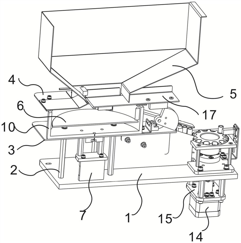
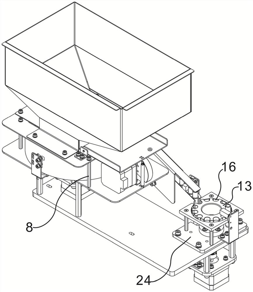
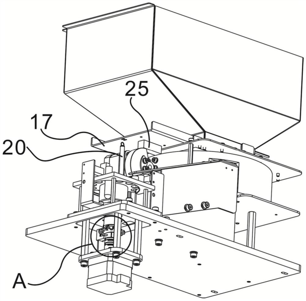
The invention provides an automatic feeding system. The automatic feeding system is characterized by comprising a bearing mechanism, wherein the bearing mechanism is provided with a centrifugal turntable mechanism, a track mechanism and a separation turntable mechanism, wherein the track mechanism is located between the centrifugal turntable mechanism and the separation turntable mechanism and separately connected with the centrifugal turntable mechanism and the separation turntable mechanism; the centrifugal turntable mechanism is used for dispersing parts to be separated and then conveying the parts to be separated into the track mechanism; the track mechanism receives the parts to be separated in the centrifugal turntable mechanism and conveys the parts to be separated to the separation turntable mechanism; and the separation turntable mechanism is used for separating and arranging the parts to be separated conveyed by the track mechanism one by one. The technical problem that the working efficiency is low in the manual adding process is solved through the automatic feeding structure.

Description

technical field [0001] The invention relates to the field of medical testing equipment, in particular to an automatic feeding system. Background technique [0002] During the testing process of the automatic immunoassay analyzer, samples and reagents need to be injected into the disposable reaction container (reaction cup), so the reaction cup as a consumable will gradually decrease during the test process; with the gradual reduction of the reaction cup , for the continuity of the test of the immune analyzer, it is necessary to add the reduced cuvettes in time, but most of the instruments currently use the method of manually adding or replacing the cuvette box as a whole. This operation will affect the working efficiency of the instrument and must be timely The cuvette can only be operated when the cuvette is used up or the instrument is shut down, which greatly affects the working efficiency of the instrument. [0003] In view of this, the present invention is proposed. ...

Claims


Application Information

Patent Timeline
Patent Type & Authority Applications(China)
IPC IPC(8): B65G47/14B65G47/26B65G47/88B65G47/82B65G65/44
CPCB65G47/1421B65G47/26B65G47/88B65G47/82B65G65/44
Inventor 李东琦刘太文王浩民
Owner 北京胡曼智造科技有限责任公司
Learn More