Low speed flow adjustable shock absorber piston

A shock absorber and piston technology, applied in shock absorbers, springs/shock absorbers, shock absorbers, etc., can solve problems such as the need to improve the shock absorption experience, the poor effect of shock absorbers, and the complex structure, and achieve easy Manufacture and assembly, compact structure, effect of few piston parts

Active Publication Date: 2022-05-24
NINGBO RUIFENG AUTO PARTS
View PDF17 Cites 2 Cited by
  • Summary
  • Abstract
  • Description
  • Claims
  • Application Information

AI Technical Summary

Problems solved by technology

[0004] However, various types of shock absorbers in the prior art have relatively complex structures, and have different shock absorption effects for different degrees of vibration, and the actual shock absorption experience needs to be improved.
Especially for the balance of the damping effect under low-velocity flow conditions and the damping effect under normal working conditions and high-speed working conditions, the existing shock absorbers are not effective and have complex structures

Method used


Image

  • Low speed flow adjustable shock absorber piston
  • Low speed flow adjustable shock absorber piston
  • Low speed flow adjustable shock absorber piston

Examples


Embodiment 1

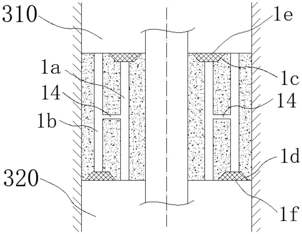
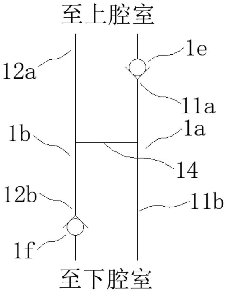
[0068] like figure 1 , 2 As shown, a low-speed flow-adjustable shock absorber piston (referred to as a piston) includes a piston body for fitting in a piston cavity. After fitting, an upper chamber 310 is formed above the piston body, and a lower chamber 320 is formed below. .

[0069] The piston also includes a number of first channel groups 1a and a number of second channel groups 1b penetrating the piston body respectively to communicate with the upper and lower chambers; the piston body also includes a first valve position 1c arranged on its upper end surface and a first valve position 1c arranged on its lower end surface. The second valve position 1d, the first channel group 1a is communicated with the first valve position 1c to open or close the first channel group 1a and the upper chamber 310 through the first valve member 1e disposed at the first valve position 1c The first valve member 1e controls whether the first channel group 1a is connected up and down; the seco...

Embodiment 2

[0076] like Figure 3-10 As shown, a low-speed flow-adjustable shock absorber piston (referred to as a piston) includes a piston body for fitting in a piston cavity. After fitting, an upper chamber 310 is formed above the piston body, and a lower chamber 320 is formed below. .

[0077] The piston further includes several first channel groups and several second channel groups respectively penetrating the piston body to communicate with the upper and lower chambers.

[0078] The piston is composed of a first piston A and a second piston B that cooperate with each other. The first piston A and the second piston B are respectively in the shape of a cylinder or a cylinder-like shape. The lower end of the first piston A and the upper end of the second piston B cooperate to form the piston.

[0079] The first piston A has a first piston upper end surface 101, a first piston side wall 102 and a first piston lower end surface 103, the first piston A is also provided with a first cent...

Embodiment 3

[0109] like Figure 11 As shown, a low-speed flow-adjustable shock absorber piston (referred to as a piston) includes a piston body for fitting in a piston cavity. After fitting, an upper chamber 310 is formed above the piston body, and a lower chamber 320 is formed below. . The main structure is the same as that of the second embodiment, and the only difference is that the setting position of the adjustment channel 14 of the present embodiment is different from that of the second embodiment.

[0110] In this embodiment, the bottom surface of the first piston A is flat, and the upper end surface 201 of the second piston is provided with an adjustment channel 14 . Moreover, in this embodiment, the adjustment channel 14 communicates with all the first and second channels.


PUM


Abstract

The invention discloses a shock absorber piston with adjustable low-speed flow. Fluid flows in or out through two channel groups arranged in the piston. Inflow from one channel group and flow out from the other channel group; and, the piston also includes an adjustment channel connecting the two channel groups, which allows the fluid to flow between the upper and lower chambers when the two one-way valves are in a closed state at low speed flow Between flow, so that the piston has the effect of low-speed flow adjustable.

Description

technical field [0001] The invention relates to the technical field of shock absorber accessories, in particular to a shock absorber piston with adjustable low-speed flow. Background technique [0002] Shock absorbers are important components of vehicles (such as automobiles and rail vehicles). Existing rail vehicles (such as high-speed EMUs, locomotives, light rails, subways, etc.) or automobiles are widely used shock absorbers for shock absorption. The function is to reduce the vibration and shock caused by the contact between the wheels and the track or the ground during the operation of the vehicle, so as to improve the safety, stability and comfort of the vehicle operation. [0003] The shock absorber is arranged between the frame and the axle. When there is a relative movement such as vibration between the two, the up and down displacement of the piston causes the oil to flow from one chamber to the other, so that the oil can flow through it. The viscous force and fri...

Claims


Application Information

Patent Timeline
Patent Type & Authority Patents(China)
IPC IPC(8): F16F9/32F16F9/34F16F9/348
CPCF16F9/3214F16F9/3405F16F9/3482F16F9/3481F16F2222/12
Inventor 邬建尧
Owner NINGBO RUIFENG AUTO PARTS
Why Eureka
Try Eureka