
Near field optical virtual optical probe

A near-field optics and virtual light technology, applied in the fields of near-field optics and nano-optics, can solve the problem of low light-passing efficiency of fiber probes

Inactive Publication Date: 2004-02-25
TSINGHUA UNIV
View PDF0 Cites 0 Cited by
  • Summary
  • Abstract
  • Description
  • Claims
  • Application Information

AI Technical Summary

Problems solved by technology

[0003] The purpose of the present invention is to overcome the shortcomings of the existing optical fiber probes such as low light transmission efficiency and the strict spacing control requirements in the SIL system, and propose a near-field optical virtual optical probe and its implementation method

Method used


Image

  • Near field optical virtual optical probe
  • Near field optical virtual optical probe
  • Near field optical virtual optical probe

Examples


Embodiment 1

[0026]Embodiment 1 is a near-field optical virtual optical probe system using isosceles right-angled triangular prisms, and its principle structure is as follows Picture 10 Shown. The system is mainly composed of Picture 10 The illustrated isosceles right-angled triangular prism 13 placed in the air 15 and a square aperture diaphragm 14 located at the interface between the prism and the air. The two acute angles θ of the isosceles right-angled triangular prism are both 45 degrees, the length of the hypotenuse is 1 cm, and the thickness of the prism is 0.7 cm. The prism material uses K9 glass with a refractive index n=1.5163. A silver film with a thickness of 100 nm is plated on the inclined surface of the prism, and a square hole 16 is opened in the center of the film layer, that is, a square aperture diaphragm 14 is formed. Its cross-sectional view is as Picture 11 As shown, 17 is a metal film, 18 is a square small hole, and its length L and width H are both 1.5 μm. When two p...

Embodiment 2

[0027] Embodiment 2 is a near-field optical virtual optical probe system using a hemispherical solid immersion lens, and its principle structure is as follows Picture 12 Shown. The system is mainly composed of Picture 12 The illustrated annular diaphragm 21, focusing objective lens 22, hemispherical solid immersion lens (SIL) 23 and square aperture diaphragm 24 are composed. The hemispherical solid immersion lens is made of ZF6 glass with a refractive index of 1.8, and its radius is 1mm. A gold film with a thickness of 150 nm is plated on the bottom surface of the solid immersion lens, and a square hole 25 is opened in the center of the film layer, that is, a square aperture diaphragm 24 is formed. Its cross-sectional view is as Figure 13 As shown, 29 is a metal film, and 30 is a square small hole, the length L and width H of which are both 1.5 μm. The annular diaphragm 21 is placed in front of the focusing objective lens, and the circular light blocking part 20 at the center t...


PUM


Abstract

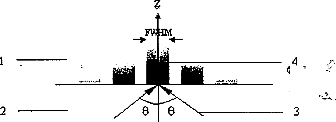
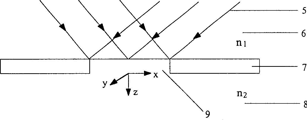
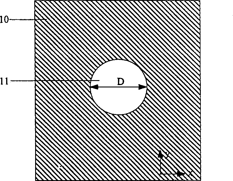
The present invention relates to a near field optical virtual probe, and is characterized by that a small-hole diaphragm is set at interface place of two media with different refractivities so as to make the evanscent field interferences produced when the incident beam whose in incident angle is greater than critical angle produces total reflection overlap to form constrained optical field, and the central peak of said constrained optical field can be formed into near field optical virtual probe. Its light-flux efficiency is high, and is 10 to the power 2-10 to the power 4 times that of general nano aperture optical fibre probe, and the half-peak value width of middle pek of its optical field distribution (i.e. size is virtual optical probe) can be basically retained and unchanged in the wavelength depth space range. It can be used in near-field optical spectral detectino, near-field optical storage, nano p hotoetching and near-field optical operation, etc.

Description

Technical field [0001] The invention belongs to the technical fields of near-field optics and nano-optics, and particularly relates to the design of a constrained light field formed by the interference superposition of an evanescent field and a nano-scale near-field optical virtual optical probe. Background technique [0002] Obtaining nano-scale light sources is one of the key technologies in near-field optical imaging, detection, nanolithography, and near-field optical storage systems. Metal-coated fiber probes with nano-aperture have been widely used in the past ten years. However, the light-passing efficiency of fiber probes is very low, usually 10 -4 ~10 -6 . Later, in the field of near-field optical imaging and near-field optical storage, the use of solid immersion lenses (Solid Immersion Lens, SIL) greatly improved the light transmission efficiency. However, this method and the fiber probe have a common disadvantage that the distance between the bottom surface of the SIL o...

Claims


Application Information

Patent Timeline
Patent Type & Authority Patents(China)
IPC IPC(8): G02B21/00G02B27/00G02B27/09G02B27/60
Inventor 王佳洪涛孙利群许吉英田芊
Owner TSINGHUA UNIV
Learn More