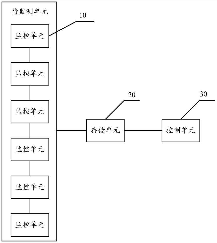
Equipment state monitoring system based on data training

A technology of equipment status and monitoring system, which is applied in the direction of electrical digital data processing, hardware monitoring, error detection/correction, etc., can solve the problems of reduced synergistic work efficiency, rough equipment status monitoring, and affecting production efficiency, so as to ensure safety and stability Operation, improvement of monitoring efficiency, reasonable and efficient work status scheduling

Active Publication Date: 2022-01-28
JIANGSU DINGCHI ELECTRONICS TECH
View PDF14 Cites 1 Cited by
  • Summary
  • Abstract
  • Description
  • Claims
  • Application Information

AI Technical Summary

Problems solved by technology

[0003] In the process of working with multi-cooperative devices or multi-cooperative components, it is necessary for each coordinating device or coordinating component to complete its own work, as well as to complete the interaction with adjacent devices or components, so that the work coordination is complete. The performance requirements are higher, but in the actual use process, the working status of each device or component is not necessarily perfect, or the job is done very well, but in the process of interacting with other devices, the status is average. As a result, the overall work efficiency of the synergy will be reduced, and even other more adverse consequences will be caused, which will affect the production efficiency.
Therefore, it is particularly important to monitor the working status of each cooperative device or cooperative component, and it has become a key point that people need to monitor urgently. However, the monitoring of devices in the prior art is still in its infancy. Comparison is for judgment, so the monitoring of equipment status is too rough

Method used


Image

  • Equipment state monitoring system based on data training

Examples


Embodiment Construction

[0041] In order to make the objects and advantages of the present invention clearer, the present invention will be further described below in conjunction with the examples; it should be understood that the specific examples described here are only for explaining the present invention, and are not intended to limit the present invention.

[0042] Preferred embodiments of the present invention are described below with reference to the accompanying drawings. Those skilled in the art should understand that these embodiments are only used to explain the technical principle of the present invention, and are not intended to limit the protection scope of the present invention.

[0043] It should be noted that, in the description of the present invention, terms such as "upper", "lower", "left", "right", "inner", "outer" and other indicated directions or positional relationships are based on the terms shown in the accompanying drawings. The direction or positional relationship shown is ...


PUM


Abstract

The invention relates to an equipment state monitoring system based on data training. The system comprises: a plurality of monitoring units, which are disposed on to-be-monitored units, and are used for monitoring operation states of the to-be-monitored units in real time; a storage unit, which is used for storing action coefficients among the monitoring units and determining to-be-monitored units which are running at present; a control unit, which is connected with the storage unit and the monitoring units, and determines monitoring time and monitoring strength of other to-be-monitored unitsaccording to states of the currently running to-be-monitored units and the action coefficients of the to-be-monitored units and other monitoring units. By monitoring states of to-be-monitored units in real time and determining monitoring time and monitoring strength of other to-be-monitored units during monitoring according to the monitored real-time states and action relationship among the to-be-monitored units and other to-be-monitored units, and accurate monitoring of the to-be-monitored units is achieved, so that the working state scheduling of the monitored units is more reasonable and efficient.

Description

technical field [0001] The invention relates to the technical field of equipment monitoring, in particular to an equipment status monitoring system based on data training. Background technique [0002] In an industrial environment where multi-equipment works together, or when a piece of equipment with multiple linkages is performing cooperative work, due to the existence of multiple cooperative equipment or multiple cooperative components, such as in the coal mine production process, it is necessary to use the conveyor belt The cinder is transported from a distance, so it is necessary to set up multiple idlers under the conveyor belt to drive the conveyor belt to work and realize the transportation. Therefore, these multiple idlers belong to multiple cooperative components, and multiple idlers are required in the steel production process. Sequential operation of coordinated equipment to complete the production of steel, such as steelmaking, pouring, rolling, etc., is to use ...

Claims


Application Information

Patent Timeline
Patent Type & Authority Applications(China)
IPC IPC(8): G06F11/30
CPCG06F11/3089G06F11/3065G06F11/3055
Inventor 贾志伟孙颖
Owner JIANGSU DINGCHI ELECTRONICS TECH
Why Eureka
Try Eureka