Industrial robot center distance adjusting ring

A technology of industrial robots and center distance, applied in manipulators, manufacturing tools, etc., can solve problems such as low installation efficiency and poor transmission accuracy, and achieve the effects of improving installation efficiency, improving production convenience, and simplifying shapes

Pending Publication Date: 2022-02-01
伯朗特机器人股份有限公司
View PDF6 Cites 0 Cited by
  • Summary
  • Abstract
  • Description
  • Claims
  • Application Information

AI Technical Summary

Problems solved by technology

In the existing technology, adjusting the meshing parameters between the gears often needs to go through the process of finding the cause of the error, repeatedly disassembling the equipment and debugging, resulting in low installation efficiency and poor transmission accuracy

Method used


Image

  • Industrial robot center distance adjusting ring
  • Industrial robot center distance adjusting ring
  • Industrial robot center distance adjusting ring

Examples


Embodiment Construction

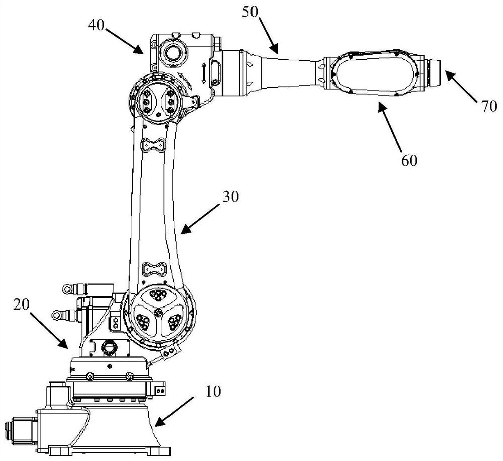
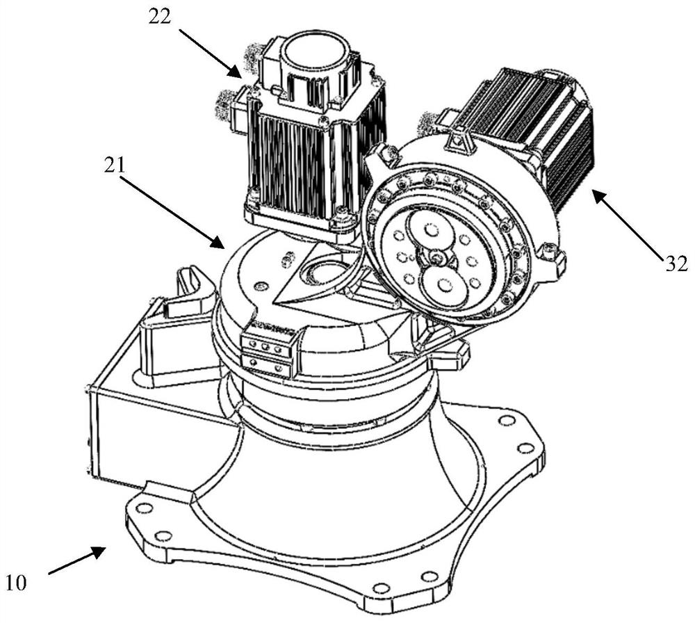
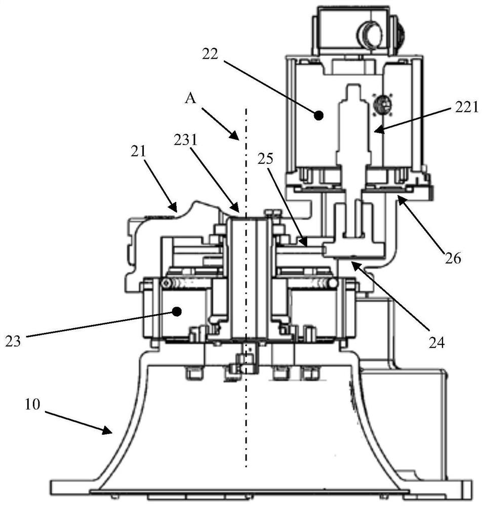
[0031] During the installation process of the components of each joint of the industrial robot, the machining error of each component and the installation error are progressive and finally affect the meshing parameters between the output gear of the motor and the input gear of the reducer, while the output gear of the motor and the input gear of the reducer The error between the gears can be eliminated by adjusting the center distance. Therefore, adjusting the distance between the output shaft of the motor and the input shaft of the reducer can correct various errors and adjust the output gear of the motor and the input gear of the reducer to the designed meshing state.

[0032] To this end, the present invention provides an industrial robot, which includes one or more joints equipped with center distance adjusting rings. Install the center distance adjusting ring into the joint to adjust the center distance between the output shaft of the joint motor and the input shaft of th...


PUM


Abstract

An industrial robot center distance adjusting ring comprises a cylindrical outer ring side face. The industrial robot center distance adjusting ring is used for being fixedly connected with a driving motor or a driving speed reducer, and during connection, the axis of an output shaft of the driving motor or the axis of an input shaft of the driving speed reducer is parallel to but does not coincide with the axis of the side face of the outer ring. Compared with the prior art, the industrial robot center distance adjusting ring has the advantages that the distance between the axis of the output shaft of the motor and the axis of the input shaft of the speed reducer can be changed by rotating the center distance adjusting ring, the adjustment of the center distance between the output gear and the input gear is quickly realized, and the mounting efficiency of the industrial robot is improved.

Description

technical field [0001] The invention relates to the technical field of industrial robots, in particular to an industrial robot center distance adjusting ring. Background technique [0002] Most of the industrial robots in the prior art use a motor to drive a reducer, and then the reducer drives the joint movement for transmission. The transmission between the motor and the reducer is carried out through gear meshing. Specifically, the output shaft of the motor is provided with an output gear, the input end of the reducer is provided with an input gear, and the output end of the reducer is fixedly connected with the joint. The output gear and the input gear are meshed with each other for transmission. The power output by the motor is transmitted to the joint through the output shaft of the motor, the output gear, the input gear, and the output end of the reducer in sequence, thereby driving the joint to rotate. [0003] It can be seen from the above structure that the tran...

Claims


Application Information

Patent Timeline
Patent Type & Authority Applications(China)
IPC IPC(8): B25J19/00B25J11/00
CPCB25J19/00B25J11/00
Inventor 周文杨医华李景南郭金龙沈澎铧
Owner 伯朗特机器人股份有限公司
Why Eureka
Try Eureka