

Variable speed chain wheel structure for light load chain transmission and optimization method thereof
A variable speed sprocket and chain transmission technology, applied in the field of chain transmission, can solve problems such as untimely speed change, rider crash, chain movement failure, etc., to achieve the effect of reducing wear and scratches, smooth moving process, and great structural compatibility
- Summary
- Abstract
- Description
- Claims
- Application Information
AI Technical Summary
Problems solved by technology
Method used
Image

Examples
Embodiment Construction
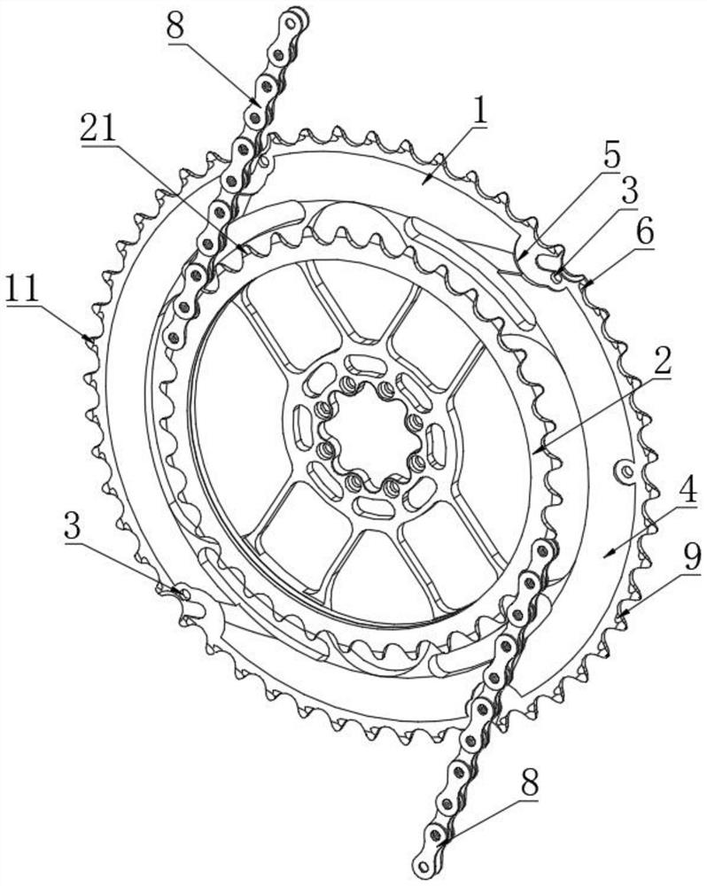
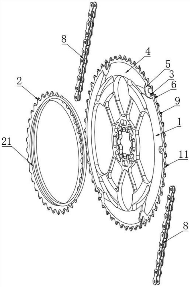
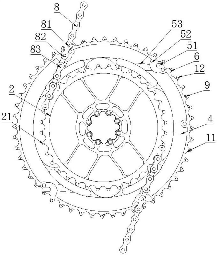
[0034] Below in conjunction with accompanying drawing and embodiment the present invention will be further described:
[0035] In the present invention, unless otherwise clearly specified and limited, terms such as "installation", "connection", "connection" and "fixation" should be understood in a broad sense, for example, it can be a fixed connection or a detachable connection , or integrated; it can be directly connected or indirectly connected through an intermediary, it can be the internal communication of two elements or the interaction relationship between two elements. Those of ordinary skill in the art can understand the specific meanings of the above terms in the present invention according to specific situations.
[0036] In the description of the present invention, it should be understood that the orientations or positional relationships indicated by the terms "left", "right", "front", "rear", "top", "bottom", etc. are based on the drawings. The orientation or posi...
PUM
| Property | Measurement | Unit |
|---|---|---|
| Thickness | aaaaa | aaaaa |
| Slope | aaaaa | aaaaa |
| Diameter | aaaaa | aaaaa |
Abstract
Description
Claims
Application Information