Cable bridge structure with high impact resistance
A cable bridge, high impact resistance technology, applied in the direction of pipe supports, electrical components, pipes/pipe joints/pipe fittings, etc., can solve the problems of low space utilization, cable accumulation, and cable bridges cannot be stored in layers, etc., to achieve Protect, speed up heat dissipation, and improve placement stability
- Summary
- Abstract
- Description
- Claims
- Application Information
AI Technical Summary
Problems solved by technology
Method used
Image

Examples
Embodiment 1
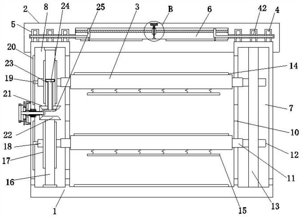
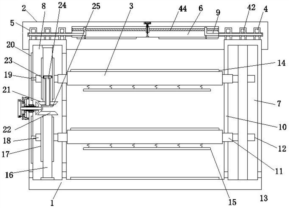
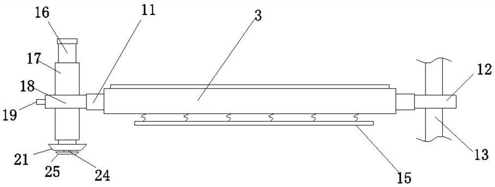
[0034] Embodiment one, by Figure 1 to Figure 7 Given, the present invention comprises a tank body 1, the top of the tank body 1 is provided with a tank cover 2, the inside of the tank body 1 is provided with two partitions 3 arranged in parallel, and the tops of the partition boards 3 are equidistantly provided with reinforcing ribs 14, The pressing plate 15 connected to the bottom of the partition 3, through the design of the pressing plate 15, facilitates the pressing of the cables, thereby improving the stability of the placement of the cables. The two sides of the top of the tank body 1 are provided with protrusions 4 at equal distances, The bottom end of the slot cover 2 is provided with a groove 5 sleeved on the outside of the bump 4. Through the snap-fit design of the bump 4 and the groove 5, the tightness of the connection between the slot cover 2 and the tank body 1 is improved, and the tank body is prevented from 1 and the tank cover 2 appear to be connected and m...
Embodiment 2
[0037] Embodiment two, on the basis of embodiment one, by figure 1 , figure 2 , image 3 , Figure 4 , Figure 5 and Figure 6 Given, the stabilizing group includes a sliding bar 11, a sliding block 12 and a stabilizing bar 13, the two ends of the two partitions 3 are provided with a sliding bar 11, the sliding bar 11 runs through the inside of the slot 10, and the other sliding bar 11 One end of each is provided with a slide block 12, and the interior of the accommodation groove 7 is provided with a stabilizer bar 13 that is slidably connected with the slide block 12. The height adjustment mechanism includes a drive group, a height adjustment group and a distance adjustment group, and the height adjustment group includes a rotating shaft 16 , threaded sleeve 17, threaded block 18, bevel gear one 21 and bevel gear two 22, two rotating shafts 16 are respectively installed in the inner top and inner bottom end of receiving groove three 8, and the outside of rotating shaft 1...
Embodiment 3
[0039] Embodiment three, on the basis of embodiment one, by figure 1 , figure 2 , Figure 4 , Figure 5 and Figure 6 Given, the spacing adjustment group includes a mounting groove 23, a mounting rod 24, a bevel gear three 25, a through groove 30, a rotating shaft 32, a rotating knob two 33, a bayonet two 34 and a bevel gear five 35, and one of the rotating shafts 16 The inside of the mounting groove 23 is provided with a mounting groove 23, and the inside of the mounting groove 23 is connected with a mounting rod 24, and the bottom end of the mounting rod 24 is provided with a bevel gear three 25, and the bevel gear three 25 is located at the bevel gear one 21 and the bevel gear two 22 Between, the inside of rotary knob one 29, T-shaped screw rod 27 and bevel gear four 28 is provided with through groove 30, and the inside of through groove 30 is interspersed with rotating shaft 32, and one end of rotating shaft 32 is provided with bevel gear three 25 The bevel gear 5 35 ...
PUM
 Abstract
Description
Claims
Application Information
 - R&D
- Intellectual Property
- Life Sciences
- Materials
- Tech Scout
- Unparalleled Data Quality
- Higher Quality Content
- 60% Fewer Hallucinations
Browse by: Latest US Patents, China's latest patents, Technical Efficacy Thesaurus, Application Domain, Technology Topic, Popular Technical Reports.
© 2025 PatSnap. All rights reserved.Legal|Privacy policy|Modern Slavery Act Transparency Statement|Sitemap|About US| Contact US: help@patsnap.com