Printing ink sand mill grinding cylinder and grinding method
A grinding cylinder and sand mill technology, which is applied in the field of grinding cylinders, can solve the problems of not being able to disperse the materials to be ground, unfavorable use, and blocking the discharge port, etc.
- Summary
- Abstract
- Description
- Claims
- Application Information
AI Technical Summary
Problems solved by technology
Method used
Image
Examples
Embodiment 1
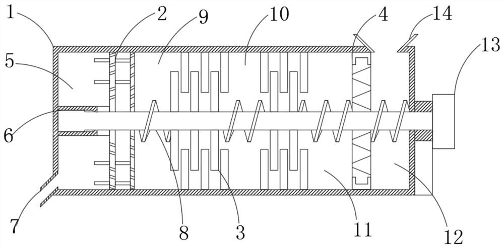
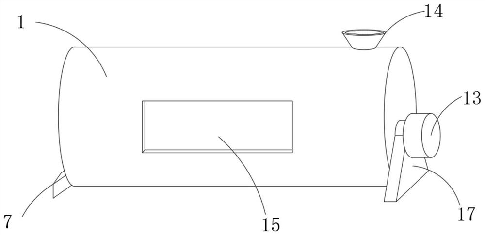
[0033] Such as Figure 1-4 As shown, a grinding cylinder of an ink sand mill and a grinding method include a grinding cylinder main body 1, the lower end of the grinding cylinder main body 1 is provided with a discharge port 7, and the inner side of the grinding cylinder main body 1 is provided with a discharge chamber 5, and the discharge chamber One side of 5 is fixedly connected with rotating shaft positioning groove 6, and the inner side of rotating shaft positioning groove 6 is fixedly connected with rotating shaft 8, and the outside of rotating shaft 8 is fixedly connected with heavy surplus stirring mechanism 2, and one side of heavy surplus stirring mechanism 2 is provided with a No. Material conveying chamber 9.
[0034] One side of the No. 1 material conveying chamber 9 is fixedly connected with a grinding wheel mechanism 3, and one side of the grinding wheel mechanism 3 is provided with a No. 2 material conveying chamber 10, a No. 3 material conveying chamber 11, an...
Embodiment 2
[0042] Such as Figure 1-3 , 5, a kind of ink sand mill grinding cylinder and grinding method, comprising grinding cylinder main body 1, the lower end of grinding cylinder main body 1 is provided with discharge port 7, the inner side of grinding cylinder main body 1 is provided with discharge cavity 5, and One side of the material cavity 5 is fixedly connected with a rotating shaft positioning groove 6, the inner side of the rotating shaft positioning groove 6 is fixedly connected with a rotating shaft 8, and the outer side of the rotating shaft 8 is fixedly connected with a heavy stirring mechanism 2, and one side of the heavy stirring mechanism 2 is provided There is a No. 9 material conveying cavity.
[0043] One side of the No. 1 material conveying chamber 9 is fixedly connected with a grinding wheel mechanism 3, and one side of the grinding wheel mechanism 3 is provided with a No. 2 material conveying chamber 10, a No. 3 material conveying chamber 11, and a The side is f...
Embodiment 3
[0051] Such as Figure 1-3 , shown in 6 and 7, an ink sand mill grinding cylinder and grinding method, comprising a grinding cylinder main body 1, the lower end of the grinding cylinder main body 1 is provided with a discharge port 7, and the inner side of the grinding cylinder main body 1 is provided with a discharge chamber 5 One side of the discharge chamber 5 is fixedly connected with a rotating shaft positioning groove 6, the inner side of the rotating shaft positioning groove 6 is fixedly connected with a rotating shaft 8, and the outer side of the rotating shaft 8 is fixedly connected with a heavy residual stirring mechanism 2, and one part of the heavy residual stirring mechanism 2 A No. 1 material conveying chamber 9 is provided on the side.
[0052] One side of the No. 1 material conveying chamber 9 is fixedly connected with a grinding wheel mechanism 3, and one side of the grinding wheel mechanism 3 is provided with a No. 2 material conveying chamber 10, a No. 3 mat...
PUM
 Abstract
Description
Claims
Application Information
 - R&D
- Intellectual Property
- Life Sciences
- Materials
- Tech Scout
- Unparalleled Data Quality
- Higher Quality Content
- 60% Fewer Hallucinations
Browse by: Latest US Patents, China's latest patents, Technical Efficacy Thesaurus, Application Domain, Technology Topic, Popular Technical Reports.
© 2025 PatSnap. All rights reserved.Legal|Privacy policy|Modern Slavery Act Transparency Statement|Sitemap|About US| Contact US: help@patsnap.com


