
Light-emitting device driving circuit, backlight module and display panel

A technology of light-emitting devices and driving circuits, which is applied to instruments, static indicators, etc., can solve problems such as the inability to compensate the voltage drop variation of the threshold voltage of light-emitting devices, power supply signals, etc., and achieve the effect of improving stability

Pending Publication Date: 2022-02-08
TCL CHINA STAR OPTOELECTRONICS TECH CO LTD
View PDF6 Cites 1 Cited by
  • Summary
  • Abstract
  • Description
  • Claims
  • Application Information

AI Technical Summary

Problems solved by technology

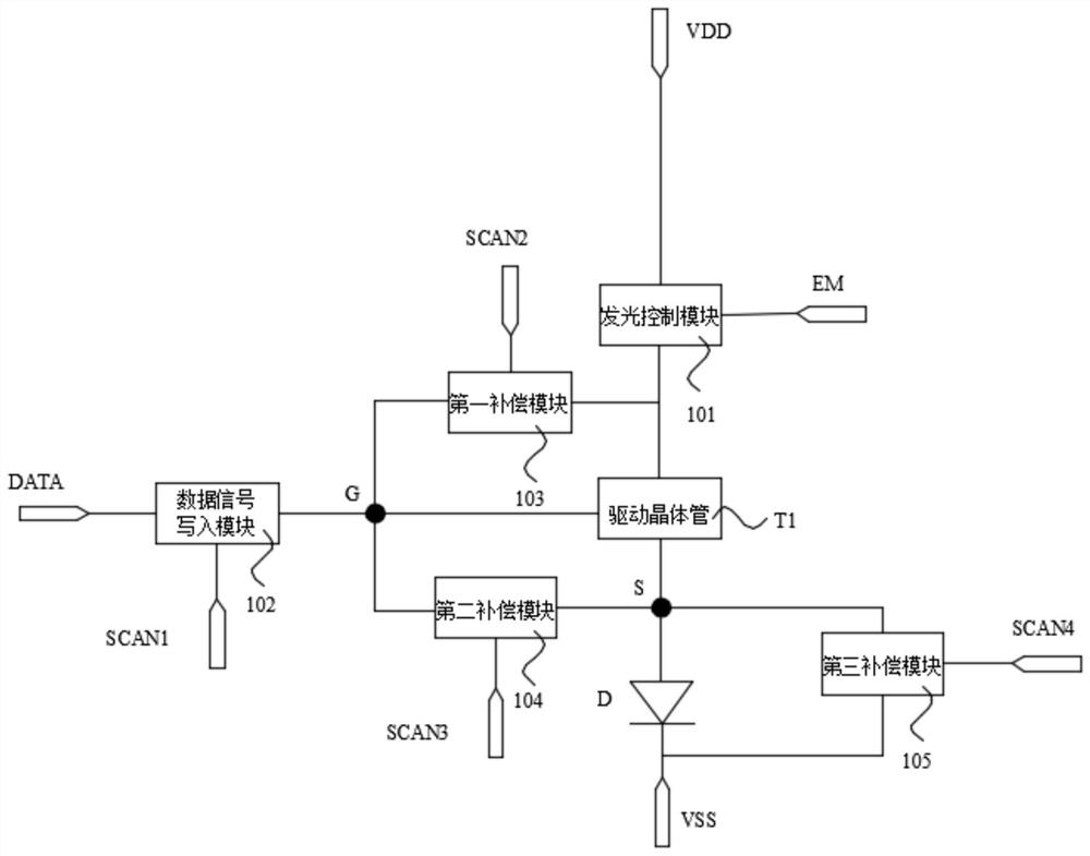
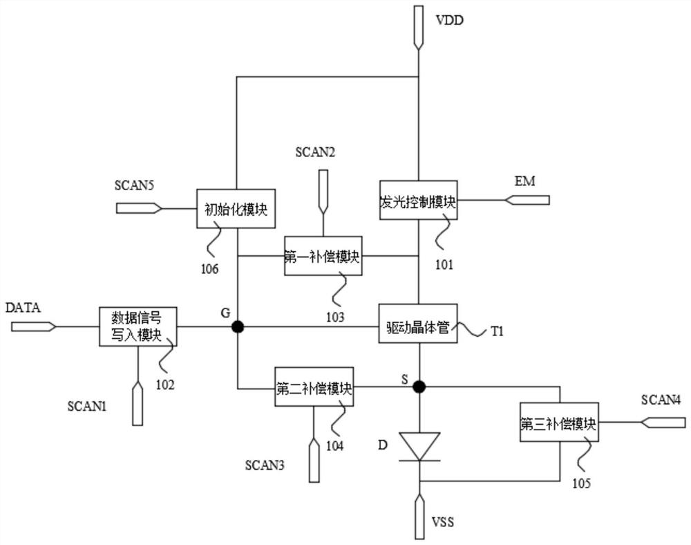
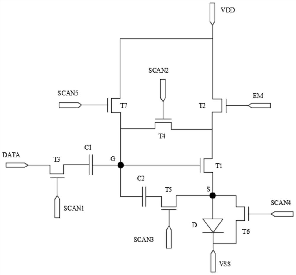
[0005] The purpose of the embodiments of the present application is to provide a light-emitting device driving circuit, a backlight module, and a display panel, which can solve the technical problem that the existing light-emitting device driving circuit cannot compensate the threshold voltage of the light-emitting device and the voltage drop variation of the power signal

Method used


Image

  • Light-emitting device driving circuit, backlight module and display panel
  • Light-emitting device driving circuit, backlight module and display panel
  • Light-emitting device driving circuit, backlight module and display panel

Examples


Embodiment Construction

[0042] The technical solutions in the embodiments of the present application will be clearly and completely described below in conjunction with the drawings in the embodiments of the present application. Apparently, the described embodiments are only some of the embodiments of this application, not all of them. Based on the embodiments in this application, all other embodiments obtained by those skilled in the art without making creative efforts belong to the scope of protection of this application.

[0043]The transistors used in all embodiments of this application can be thin film transistors or field effect transistors or other devices with the same characteristics. Since the source and drain of the transistors used here are symmetrical, their source and drain can be interchanged. of. In the embodiment of the present application, in order to distinguish the two poles of the transistor except the gate, one pole is called the source, and the other pole is called the drain. ...


PUM


Abstract

The embodiment of the invention provides a light-emitting device driving circuit, a backlight module and a display panel. The light-emitting device driving circuit comprises a light-emitting device, a light-emitting control module, a driving transistor, a data signal write-in module, a first compensation module, a second compensation module and a third compensation module. The threshold voltage of the driving transistor can be compensated through the first compensation module, the threshold voltage of the light-emitting device can be compensated through the second compensation module, and the voltage drop of the light-emitting device driving circuit can be compensated through the third compensation module. Therefore, the problem of brightness attenuation of the light-emitting device in the light-emitting device driving circuit can be solved, and the display stability of the display panel can be improved.

Description

technical field [0001] The present application relates to the field of display technology, in particular to a light emitting device driving circuit, a backlight module and a display panel. Background technique [0002] At present, display devices are mainly divided into two types: passive driving and active driving. Among them, the passive driving method has the advantage of low cost, but it is difficult to achieve high resolution due to the existence of crosstalk, and the corresponding transient current of the light emitting diode is too large, resulting in a short service life of the power supply and the display device. The active drive is equipped with a thin film transistor for each pixel, and the existence of capacitors avoids the problems of crosstalk and excessive transient current. Therefore, the existing display devices usually adopt the active drive method, thereby improving the The life of the display device is improved, and the power consumption of the display d...

Claims


Application Information

Patent Timeline
IPC IPC(8): G09G3/32G09G3/3208
CPCG09G3/32G09G3/3208G09G2320/0233G09G2310/0264
Inventor 刘斌刘全胜
Owner TCL CHINA STAR OPTOELECTRONICS TECH CO LTD
Learn More