Self-compensating J-shaped wire clamp installer

An installer and self-compensation technology, which is applied in the direction of equipment for connecting/terminating cables, etc., can solve problems such as failure of parallel grooves, low efficiency of J-shaped clamps, and low clamping force of clamps, so as to improve safety and efficiency performance, improve the actual installation efficiency, and improve the effect of using safety

Pending Publication Date: 2022-02-08
HEFEI CAS LANRUI TECH CO LTD
View PDF0 Cites 0 Cited by
  • Summary
  • Abstract
  • Description
  • Claims
  • Application Information

AI Technical Summary

Problems solved by technology

However, in the above-mentioned installation process, people found that: because the screw sleeve at the striking part of the traditional clamp installer is directly driven by the striking motor and produces a rotary motion, that is, it only has a rotary motion around its own axis.
When the threaded sleeve engages with the tension nut and rotates the tension nut, the two guide blocks move relative to each other during the clamping process, and at the same time the tension nut rotates upward along the tension bolt, and the tension nut will gradually The detachment of the screw sleeve, and then the incomplete contact between the screw sleeve and the tension nut
The above-mentioned incomplete contact phenomenon, at the slightest, makes the assembly process of the J-shaped clamp inefficient, and requires frequent start-stops to hit the motor many times in order to ensure that the tension nut can rotate; As a result, the clamping force of the wire clamp is low or even the groove fails.
Once the above situation occurs, the operator will have to manually work at heights to troubleshoot, which is extremely time-consuming and laborious, which obviously brings great troubles to the actual line clip and ditch operation

Method used


Image

  • Self-compensating J-shaped wire clamp installer
  • Self-compensating J-shaped wire clamp installer
  • Self-compensating J-shaped wire clamp installer

Examples


Embodiment Construction

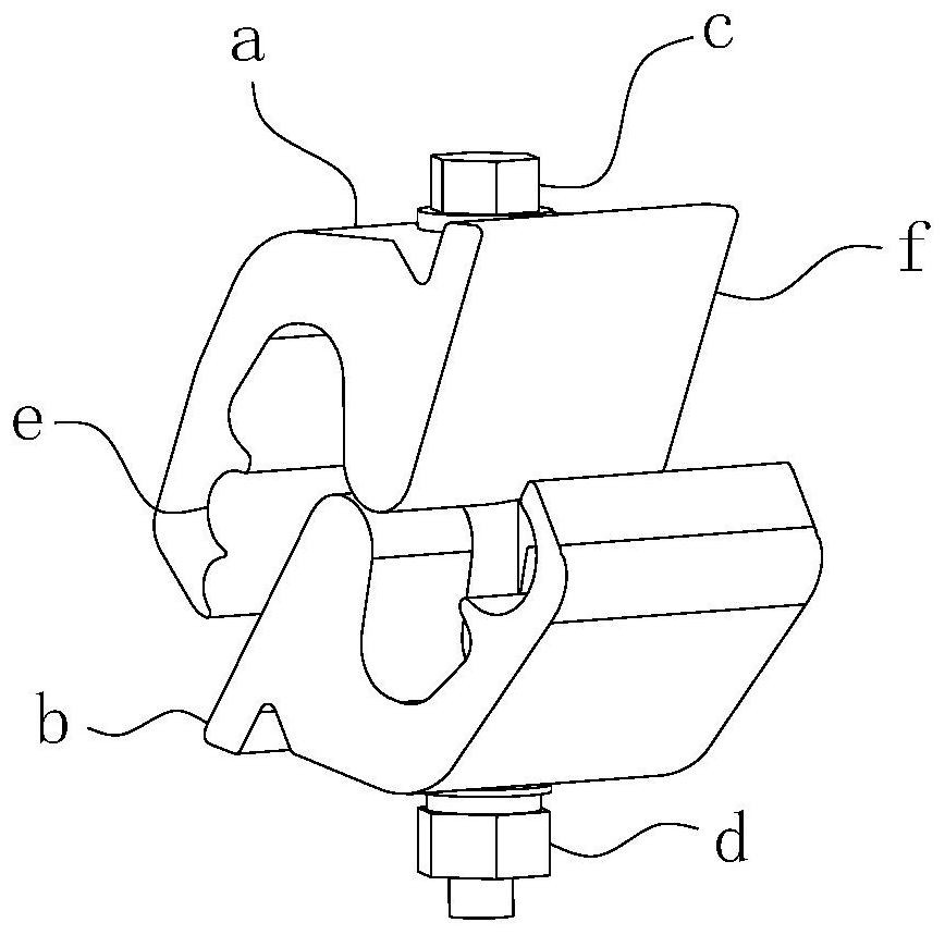
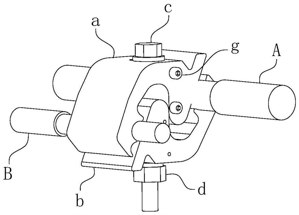
[0042] For ease of understanding, combined here Figure 1-14 , taking the installation and construction of the traditional J-shaped wire clamp as an example, the following is collectively referred to as the wire clamp, and the specific structure and working method of the present invention are further described as follows:

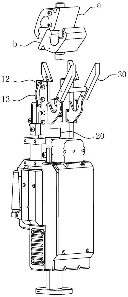
[0043] The present invention can be used in remote control equipment such as robots; during actual assembly, the present invention can be fixed on the mechanical arm. At this time, since the main line is fixed as a reference object, the present invention can be lifted by the mechanical arm to complete the relative main line. The upper top type clamp and ditch operation. The traditional line clip installation method is to hook from top to bottom relative to the main line. The present invention adopts a bottom-to-top jacking installation relative to the main line. There is no need to make a leaping action during work, so it can significantly reduce the comple...


PUM


Abstract

The invention belongs to the technical field of power equipment, and particularly relates to a self-compensating J-shaped wire clamp installer. The installer comprises a positioning mounting part, a striking part is arranged at the positioning mounting part, the striking part comprises a screw sleeve which is coaxially arranged with a to-be-rotated object, and the screw sleeve is driven by a striking motor so as to generate a coaxial rotation action relative to the to-be-rotated object; the installer further comprises a compensation assembly; the compensation assembly comprises a transmission shaft coaxially and fixedly connected to an output shaft of the striking motor, the transmission shaft is coaxially sleeved with an outer guide sleeve, the outer guide sleeve and the transmission shaft are in rotation stopping fit, and the screw sleeve is coaxially assembled at the top end of the outer guide sleeve; and the compensation assembly further comprises an elastic piece for driving the outer guide sleeve to move upwards in the axial direction relative to the transmission shaft. According to the invention, in the doubling installation process of the J-shaped wire clamp, the thread sleeve always synchronously acts along with the tightening nut or the nut of the tightening screw until the wire clamp is completely clamped in a parallel groove, so that the use safety and the actual installation efficiency of the wire clamp are greatly improved.

Description

technical field [0001] The invention belongs to the technical field of electric power equipment, and in particular relates to a self-compensating J-shaped wire clip installer. Background technique [0002] The J-shaped clamp is a non-load-bearing link clamp, which is used to connect the secondary line of the branch line of the 10kV power line to the main line of the main line. The shape reference of the J-shaped clamp figure 1 As shown, it includes two J-shaped guide blocks that engage with each other and a tension bolt that guides the two guide blocks to produce similar movements. During installation, the auxiliary line of the branch line is embedded in the slot of one of the guide blocks, and the main line of the main line is embedded in the slot of the other guide block; the two guides are tightened by the cooperation of the tension bolt and the tension nut. block, so that the auxiliary line and the main line are tightly clamped on the guide block, so that the current c...

Claims


Application Information

Patent Timeline
Patent Type & Authority Applications(China)
IPC IPC(8): H02G1/14
CPCH02G1/14
Inventor 孙丙宇孙璞姚德亮郭兴源
Owner HEFEI CAS LANRUI TECH CO LTD
Why Eureka
Try Eureka