Spot welding equipment with precise positioning structure for welding

A spot welding equipment and precise positioning technology, which is applied in welding equipment, welding equipment, auxiliary welding equipment, etc., can solve the problems of increasing the working pressure of the staff, the positioning structure is not accurate enough, and there is no rotatable workpiece welding. Market competitiveness, practicability, reasonable design effect

Pending Publication Date: 2022-02-11
JILIN UNIV
View PDF6 Cites 0 Cited by
  • Summary
  • Abstract
  • Description
  • Claims
  • Application Information

AI Technical Summary

Problems solved by technology

[0003] However, when working in the workshop, because the workpiece to be welded is large in size, it is necessary to weld at a position that can be reached by the arm. If a more comprehensive welding of the workpiece is required, it is necessary to walk to a suitable welding position and locate the structure. It is not accurate enough, and the adjustment is not convenient, which will bring a lot of workload to the staff, and some current spot welding equipment is not convenient to operate, and does not have rotatable workpiece welding, which greatly increases the working pressure of the staff. , for this purpose, we propose a spot welding equipment with precise positioning structure for welding

Method used


Image

  • Spot welding equipment with precise positioning structure for welding
  • Spot welding equipment with precise positioning structure for welding
  • Spot welding equipment with precise positioning structure for welding

Examples


Embodiment Construction

[0021] The following will clearly and completely describe the technical solutions in the embodiments of the present invention with reference to the accompanying drawings in the embodiments of the present invention. Obviously, the described embodiments are only some, not all, embodiments of the present invention.

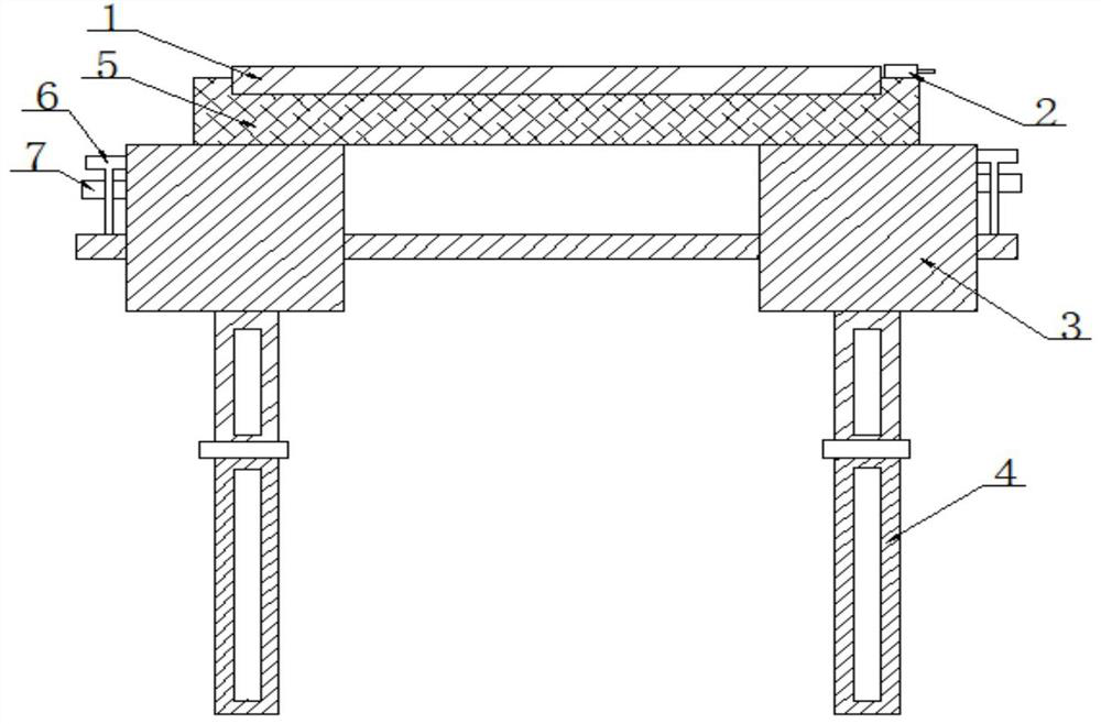
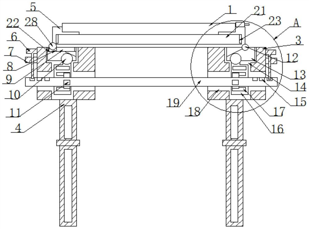
[0022] refer to Figure 1-6 , a kind of spot welding equipment with precise positioning structure for welding, including a first iron plate 1, a third iron plate 5 is installed on the bottom of the first iron plate 1, and the right bottom of the third iron plate 5 is A second rotating shaft 12 is installed, and a third rotating shaft 28 is installed on the left bottom of the third iron plate 5, and a fourth iron plate 13 is installed on the end of the second rotating shaft 12 away from the third iron plate 5. A seventh iron plate 22 is installed below the third rotating shaft 28 .

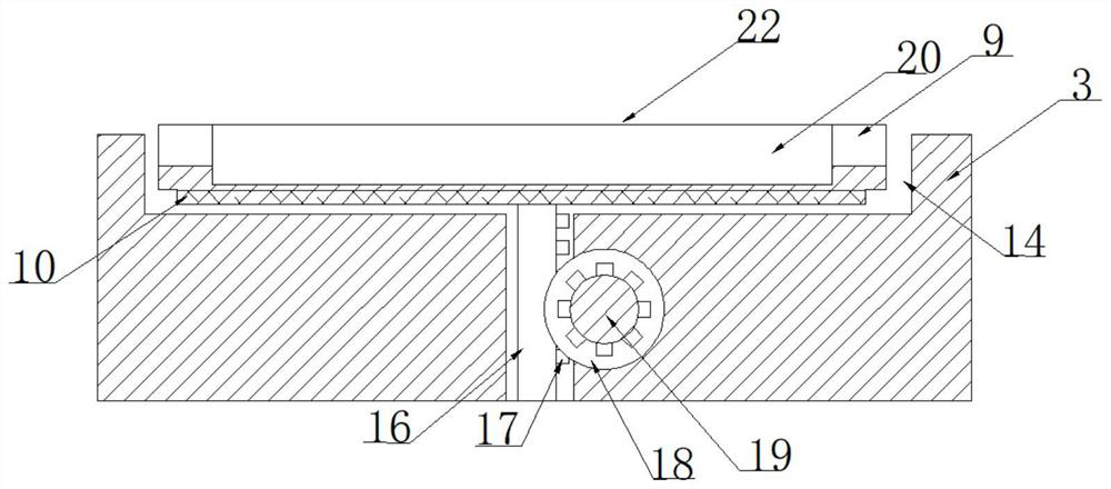
[0023] The top of the seventh iron plate 22 is provided with a first groove 9, the s...


PUM


Abstract

The invention relates to the technical field of welding, and particularly relates to spot welding equipment with a precise positioning structure for welding. The equipment comprises a first iron plate, a third iron plate is mounted at the bottom of the first iron plate, second iron plates are mounted on two sides of the bottom of the third iron plate, and a sixth iron plate is mounted in the third iron plate. The sixth iron plate rotates in the third iron plate and is rotatably connected with the first iron plate, a plurality of second grooves are formed in the sixth iron plate, a first iron rod is installed below the third iron plate, the two ends of the first iron rod penetrate through the inner walls of the second iron plates, and first grooves are formed in the two ends of the first iron rod; and gears are mounted at the two ends of the first iron rod so that the angle of an object needing to be welded is adjusted while the welding requirement is met, operation is easy and convenient, operation of workers is facilitated, the workload of the workers is reduced, and the working pressure is relieved.

Description

technical field [0001] The invention relates to the field of welding technology, in particular to spot welding equipment with a precise positioning structure for welding. Background technique [0002] Welding is a process in which two or more materials of the same or dissimilar type are connected together through the bonding and diffusion of atoms. Welding ensures the connectivity of metals and makes the welded structure more functional and reliable. , The application of spot welding equipment is also very extensive, and the demand is relatively large. Many construction sites, enterprise accessories, etc. need to be used. [0003] However, when working in the workshop, because the workpiece to be welded is large in size, it is necessary to weld at a position that can be reached by the arm. If a more comprehensive welding of the workpiece is required, it is necessary to walk to a suitable welding position and locate the structure. It is not accurate enough, and the adjustmen...

Claims


Application Information

Patent Timeline
IPC IPC(8): B23K11/36B23K11/11B23K37/04
CPCB23K11/36B23K11/11B23K37/0461
Inventor 王宏志徐国成
Owner JILIN UNIV
Why Eureka
Try Eureka