
Anti-collision fire hydrant

A fire hydrant and anti-collision technology, applied in fire rescue, water supply installations, buildings, etc., can solve problems such as long valve opening and closing time, waste of water resources, and valve blockage failure.

Inactive Publication Date: 2022-02-11
曹钢
View PDF0 Cites 0 Cited by
  • Summary
  • Abstract
  • Description
  • Claims
  • Application Information

AI Technical Summary

Problems solved by technology

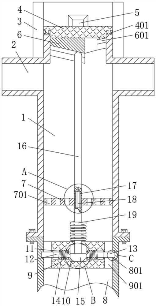
[0004] Aiming at the deficiencies in the use of the existing fire hydrant proposed in the background technology, the present invention provides an anti-collision type fire hydrant, which has the action of opening and closing the valve hole when the head rotates one turn, tilting and squeezing Press the movable rod to complete the up and down movement, and the movable rod moves up and down so that the extrusion seat squeezes the pressure rod, and the pressure rod drives the valve plate to open and close the valve hole. When the fire hydrant is impacted by external force, the movable rod forms a three-section centerline deviated rod. 1. When the fire hydrant is impacted by external force, the extrusion seat does not shift and deform. When the fire hydrant is impacted by external force, the valve plate still blocks the valve hole. When the extrusion seat is partially displaced and deformed, the valve plate performs position compensation to block the valve. The advantage of the hole solves the technical problems in the above-mentioned background technology that the opening and closing time of the valve is long, the valve is blocked due to the impact of the fire hydrant, and the water resources are sprayed out to cause waste.

Method used


Image

  • Anti-collision fire hydrant
  • Anti-collision fire hydrant
  • Anti-collision fire hydrant

Examples


Embodiment Construction

[0029] The following will clearly and completely describe the technical solutions in the embodiments of the present invention with reference to the accompanying drawings in the embodiments of the present invention. Obviously, the described embodiments are only some, not all, embodiments of the present invention. Based on the embodiments of the present invention, all other embodiments obtained by persons of ordinary skill in the art without making creative efforts belong to the protection scope of the present invention.

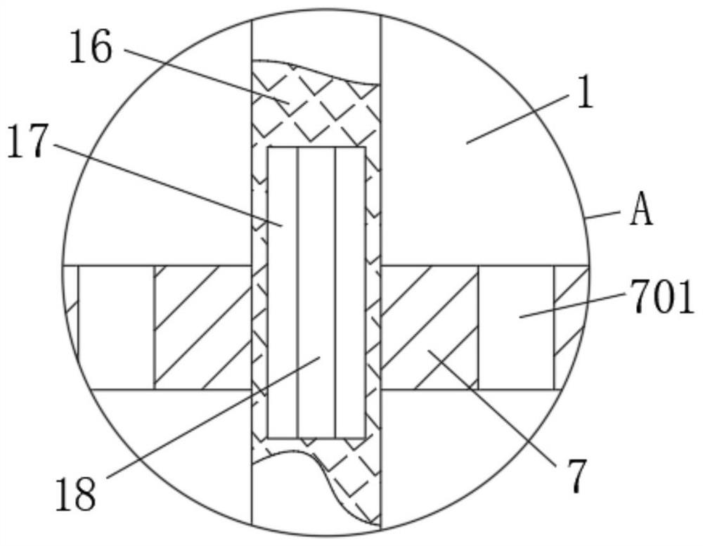
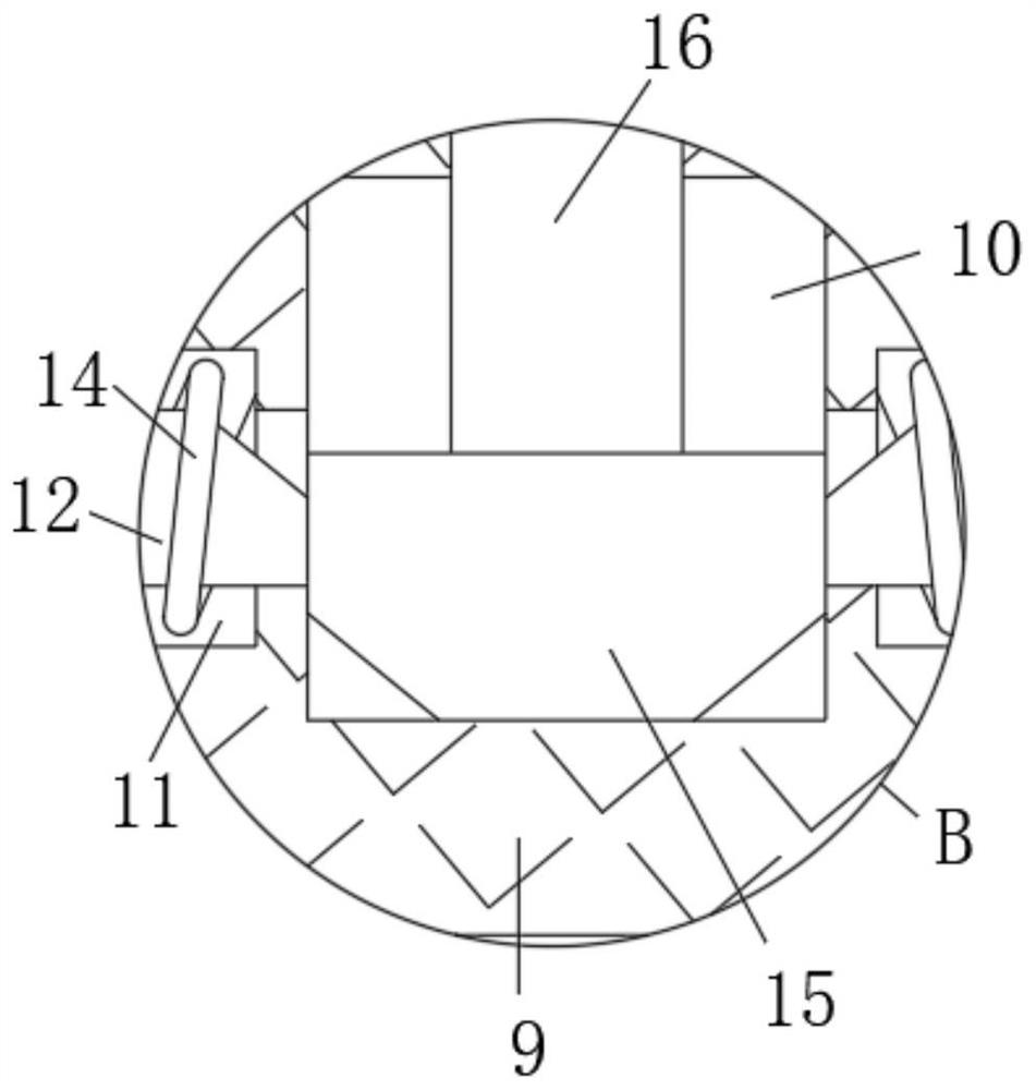
[0030] see figure 1 , Figure 5 , Figure 9 , a kind of anti-collision fire hydrant, comprising above-ground pipe 1, standard water outlet 2 on the top of above-ground pipe 1, bolt cap 3 on the top of above-ground pipe 1, the top center of above-ground pipe 1 is movably socketed with bolt cover 4, bolt cover 4 The outside of the bottom end of the bottom end is fixedly connected with the limit protrusion 401, and the top of the ground pipe 1 is provided with ...


PUM


Abstract

The invention relates to the technical field of fire rescue, and discloses an anti-collision fire hydrant which comprises an overground pipe, a standard water outlet in the top of the overground pipe and a hydrant cap at the top end of the overground pipe, the center of the top end of the overground pipe is movably sleeved with a hydrant cover, and the outer side of the bottom end of the hydrant cover is fixedly connected with a limiting protrusion. The center of the top end of the hydrant cover is fixedly connected with a rotating head, the bottom end of the hydrant cover is fixedly connected with an inclined ring, and a sliding groove is formed in the inclined ring. By designing the rotating head, the inclined ring, the movable rod, the extrusion seat, the pressed rod and the valve plate, the movable rod can be extruded and loosened in the whole process through the inclined ring when the rotating head rotates by a circle, so that the extrusion seat can extrude and loosen the pressed rod in a short time; and the valve plate can complete opening and closing of the valve hole and different opening and closing degrees in a short time, so that the fire hydrant is prevented from needing to rotate the screw rod for a long time to complete opening and closing of the valve in an emergency.

Description

technical field [0001] The invention relates to the technical field of firefighting and rescue, in particular to an anti-collision fire hydrant. Background technique [0002] Fire hydrants are fixed fire-fighting facilities, which are divided into indoor fire hydrants and outdoor fire hydrants. Most of the outdoor fire hydrants are buried beside roads, in residential areas, etc., and the buried part is connected with the municipal water pipe network. The part on the ground is equipped with a standard nozzle for easy connection with the fire hose. [0003] The main outlet and shut-off of the fire hydrant needs to turn the top rotor through the unique handle switch, so that the screw rod drives the valve stem to move up and down, so that the valve can be opened and closed. Due to the design of the screw rod, it needs to rotate many times to turn it The valve is fully opened, which makes it impossible to race against time in case of emergency. At the same time, because the exi...

Claims


Application Information

Patent Timeline
Patent Type & Authority Applications(China)
IPC IPC(8): E03B9/02E03B9/06E03B9/14
CPCE03B9/02E03B9/06E03B9/14
Inventor 曹钢
Owner 曹钢
Learn More