
Omnidirectional electron emission device based on deflection grid electrode

An electron emission device and a technology for electron beam emission, which are applied to electrode devices and related components, cathode ray tubes/electron beam tubes, circuits, etc., and can solve the problems of large size, inapplicability, and lack of emission.

Pending Publication Date: 2022-02-11
NAT SPACE SCI CENT CAS
View PDF0 Cites 0 Cited by
  • Summary
  • Abstract
  • Description
  • Claims
  • Application Information

AI Technical Summary

Problems solved by technology

However, the existing traditional technology has a large volume and is not suitable for high-precision space detection. It cannot realize 360-degree omnidirectional space detection, and the energy of emitted electrons cannot be adjusted, and it does not have the ability to emit electrons with any energy in any direction. ability

Method used


Image

  • Omnidirectional electron emission device based on deflection grid electrode
  • Omnidirectional electron emission device based on deflection grid electrode
  • Omnidirectional electron emission device based on deflection grid electrode

Examples


Embodiment Construction

[0029] The present invention will be further described in conjunction with accompanying drawing and example now.

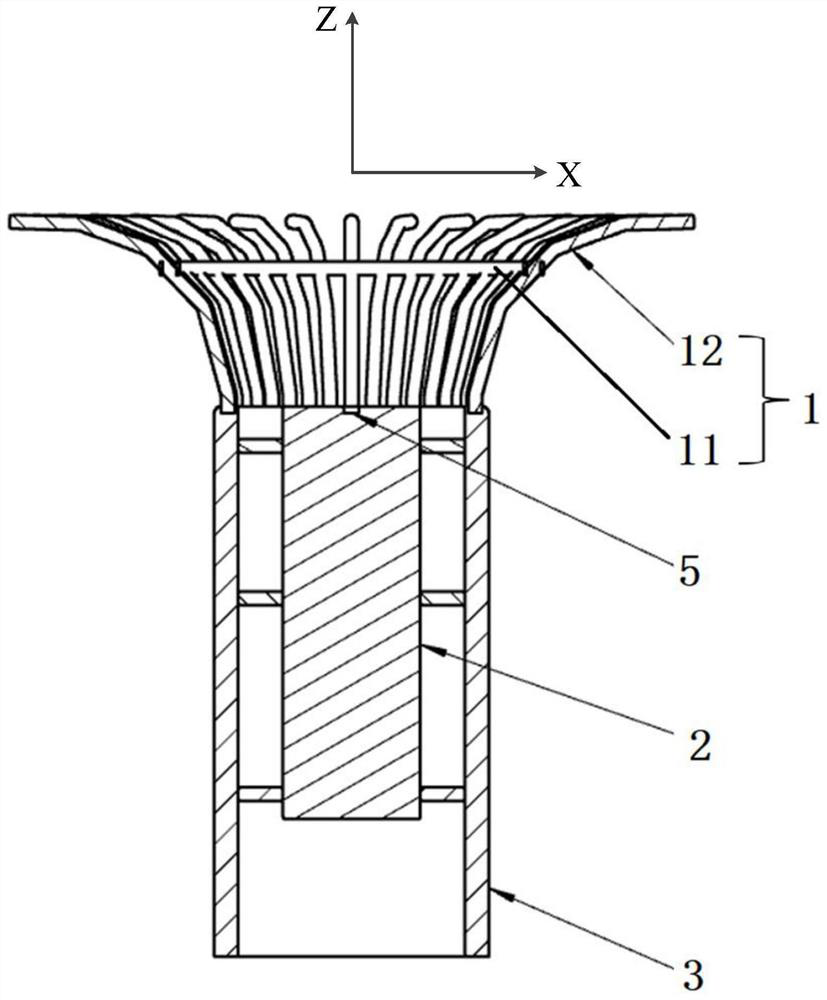
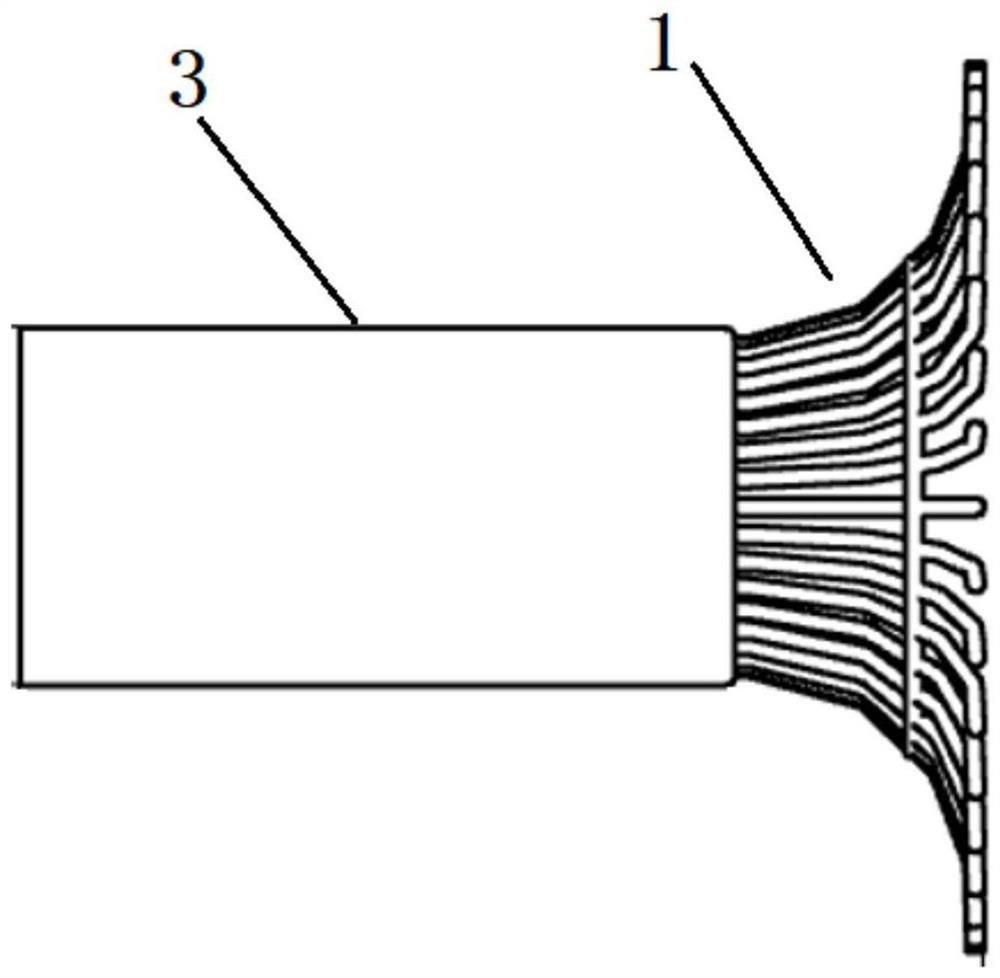
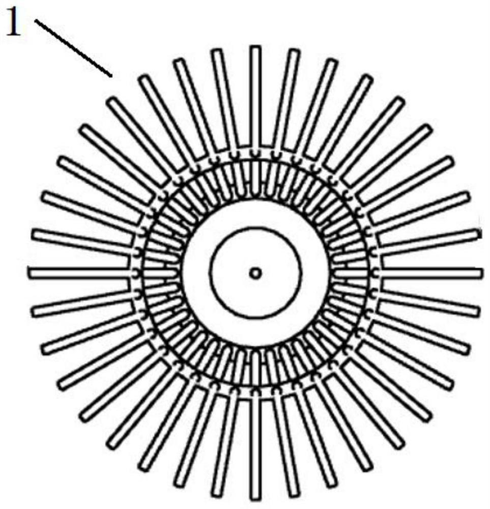
[0030] like figure 1 , 2 As shown in and 5, the present invention provides an omnidirectional electron emission device based on a deflection grid, which device includes: an omnidirectional deflection grid 1, an electron gun 2, a structural housing 3 and a logic controller 4;

[0031] The electron gun 2 is arranged in the structural housing 3, and the electron beam emission opening of the electron gun 2 is located on the central axis of the structural housing 3, and the opening provided at the top of the structural housing 3 and the electron beam emission opening of the electron gun 2 are in the same direction, And the two overlap on the same horizontal plane; the omnidirectional deflection grid 1 is arranged above the electron beam emission opening of the electron gun 2;

[0032] The omnidirectional deflection grid 1 is electrically connected with the logic cont...


PUM


Abstract

The invention belongs to the technical field of electron emitters, and particularly relates to an omnidirectional electron emission device based on a deflection grid electrode. The device comprises an omnidirectional deflection grid electrode (1), an electron gun (2), a structural shell (3) and a logic controller (4). An opening is formed in the top of the structural shell (3), the electron gun (2) is arranged in the structural shell (3), an electron beam emission opening of the electron gun (2) is located on the central axis of the structural shell (3), and the opening formed in the top of the structural shell (3) and the electron beam emission opening of the electron gun (2) are located in the same direction and are overlapped; the omnidirectional deflection grid electrode (1) is arranged on the electron beam emission opening of the electron gun (2); the omnidirectional deflection grid electrode (1) and the logic controller (4) are in electrical connection or remote communication connection; and the logic controller (4) is used for loading generated different 36 paths of high-voltage power supplies to the omnidirectional deflection grid electrode (1) to form a 360-degree omnidirectional deflection electric field.

Description

technical field [0001] The invention belongs to the technical field of electron emitters, and in particular relates to an omnidirectional electron emission device based on a deflection grid. Background technique [0002] Electron emitter (commonly known as "electron gun") is a general-purpose experimental instrument. The traditional electron emitter emits electrons with a certain energy along the axis of the "electron gun" opening. If electron emission in different directions is realized, the electron gun body can be rotated through the mechanism, or electrostatic deflection and magnetic field deflection can be performed to adjust the direction within a certain angle range. However, the existing traditional technology has a large volume and is not suitable for high-precision space detection. It cannot realize 360-degree omnidirectional space detection, and the energy of emitted electrons cannot be adjusted, and it does not have the ability to emit electrons with any energy ...

Claims


Application Information

Patent Timeline
Patent Type & Authority Applications(China)
IPC IPC(8): H01J29/48H01J29/56
CPCH01J29/485H01J29/487H01J29/563
Inventor 刘超董永进张爱兵孙越强郑香脂田峥
Owner NAT SPACE SCI CENT CAS
Learn More