
Efficient step end mill

A technology of end mills and steps, which is applied in the field of high-efficiency step end mills, can solve the problems of fast tool tip wear and short service life, and achieve the effects of improving milling processing efficiency, prolonging service life and high efficiency

Active Publication Date: 2022-03-29
ZHONGBEI UNIV
View PDF18 Cites 0 Cited by
  • Summary
  • Abstract
  • Description
  • Claims
  • Application Information

AI Technical Summary

Problems solved by technology

[0004] In order to overcome the shortcomings of the existing stepped end mills with fast tool tip wear and short service life, the present invention provides a step-distributed end mill with high milling efficiency and long service life.

Method used


Image

  • Efficient step end mill
  • Efficient step end mill
  • Efficient step end mill

Examples


Embodiment 1

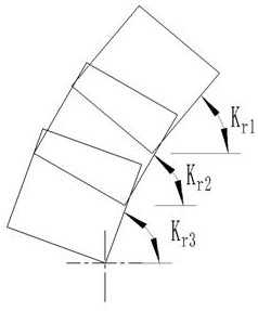
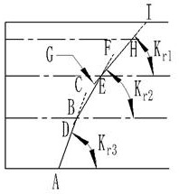
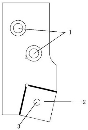
[0046] Such as Figure 1-Figure 9 As shown; now take 4 cutter groups on the cutter body, each group includes 3 cutter teeth as an example, that is, each group is divided into 3 steps, and the end mill has 12 tool seats and cutter teeth in total, which is a three-step end milling The blades of the same order have the same height and diameter, that is to say, the distances from the tip of the teeth of the same order to the end face of the cutter body are the same, and the distance to the axis of the cutter body is also equal, but the tips of the teeth of different stages are neither equal. The height is not equal to the diameter, that is, the distances from the tips of different stages of cutter teeth to the end face of the cutter body are not equal, and the distances from the axis of the cutter body are also not equal.

[0047] According to the relevant regulations of the national standard, the tool nose radius R of the third-order cutter tooth 3 , Tool tip height H 3 and cut...


PUM


Abstract

The present invention belongs to the field of end milling cutter, which involves a high -efficiency staircase end milling cutter; including the knife body, the knife body is equipped with N knife groups, each group includes M knife teeth, M knife teeth along the knife circumference of the knife body circumstances Arrived to the step -by -step ladder, that is, M to teeth for forming M stairs; the last blade teeth in the knife group as the last step, the higher the number of knife teeth, the larger the height of the knife tip. 1 <H 2 <H 3 <··· <h m ; The higher the order of the knife teeth, the smaller the radius of the knife tip, the smaller, R 1 R 2 R 3 > ···> r m ; The higher the order of the blade, the higher the corner K r The bigger, the more K r1 <k r2 <k r3 <··· <k k rm Essence The ladder design effectively improves the total cutting depth of the end milling cutter work to significantly improve its milling and processing efficiency; except for the tip of the end -order knife to teeth to participate in the cutting work, the knife tip of the other steps to teeth is milling tip milling in milling. Do not participate in cutting during the work, so that the cutting teeth except the end of the teeth can be freely cut, effectively protecting the most damaged knife tip of the knife tooth, thereby extending the life of the tool.

Description

technical field [0001] The invention belongs to the field of end mills, in particular to a high-efficiency stepped end mill. Background technique [0002] With the continuous development of manufacturing industries such as national defense, heavy machinery, heavy chemical industry, heavy electrical engineering, automobiles, railways, mining machinery, and CNC machine tools, the workload of plane milling is increasing. In cutting processing, milling processing accounts for more than 60% of cutting processing workload. This means that there is an urgent need for heavy-duty end mills to solve the problems of low efficiency and high process cost in face milling. [0003] Due to the large allowance plane milling process, there are problems of poor surface quality of the workpiece and large machining allowance. First of all, ordinary end mills are inefficient in milling and cannot perform these milling jobs efficiently. Secondly, during the working process of ordinary stepped e...

Claims


Application Information

Patent Timeline
Patent Type & Authority Patents(China)
IPC IPC(8): B23C5/06
CPCB23C5/06
Inventor 唐志雄黄晓斌闫凯强孙宝雨赵慧瑜
Owner ZHONGBEI UNIV
Learn More