Top frame welding clamp

A welding fixture and top frame technology, which is applied in welding equipment, auxiliary welding equipment, welding/cutting auxiliary equipment, etc., can solve the problems of poor versatility and inability to clamp and fasten the top frame, and achieve the effect of improving versatility

Pending Publication Date: 2022-02-15
江苏鲁安特智能装备科技有限公司
View PDF0 Cites 1 Cited by
  • Summary
  • Abstract
  • Description
  • Claims
  • Application Information

AI Technical Summary

Problems solved by technology

[0003] The purpose of the present invention is to overcome the deficiencies in the prior art, provide a top frame welding jig, and solve the technical problem that the top frame welding jig in the prior art has poor versatility and cannot really clamp and fasten the top frame

Method used


Image

  • Top frame welding clamp
  • Top frame welding clamp
  • Top frame welding clamp

Examples


Embodiment Construction

[0024] The present invention will be further described below in conjunction with the accompanying drawings. The following examples are only used to illustrate the technical solution of the present invention more clearly, but not to limit the protection scope of the present invention.

[0025] In describing the present invention, it should be understood that the terms "center", "longitudinal", "transverse", "upper", "lower", "front", "rear", "left", "right", " The orientations or positional relationships indicated by "vertical", "horizontal", "top", "bottom", "inner" and "outer" are based on the orientations or positional relationships shown in the drawings, and are only for the convenience of describing the present invention and Simplified descriptions, rather than indicating or implying that the device or element referred to must have a particular orientation, be constructed and operate in a particular orientation, and thus should not be construed as limiting the invention. ...


PUM


Abstract

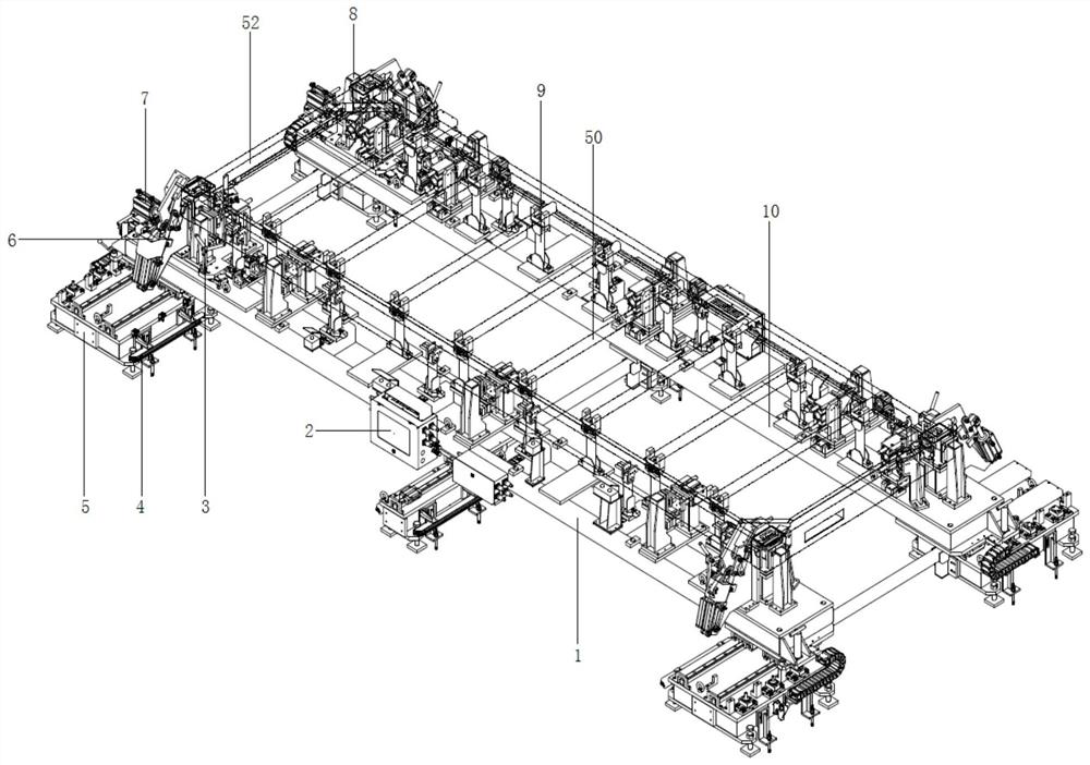
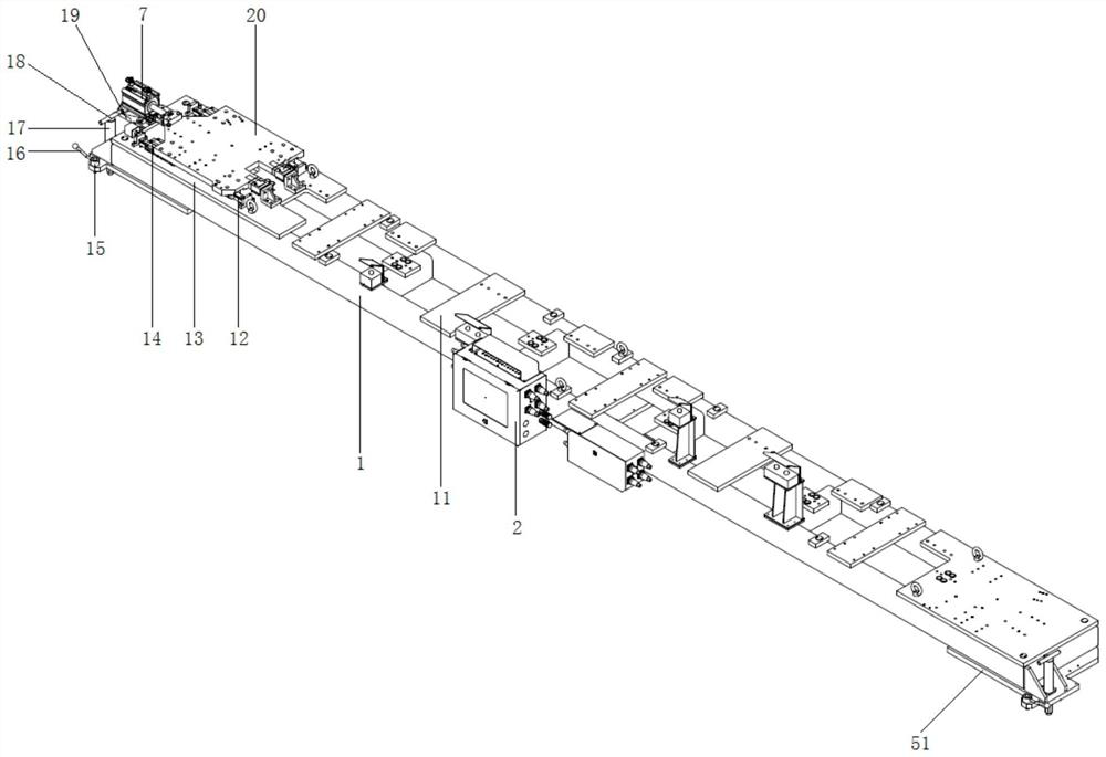
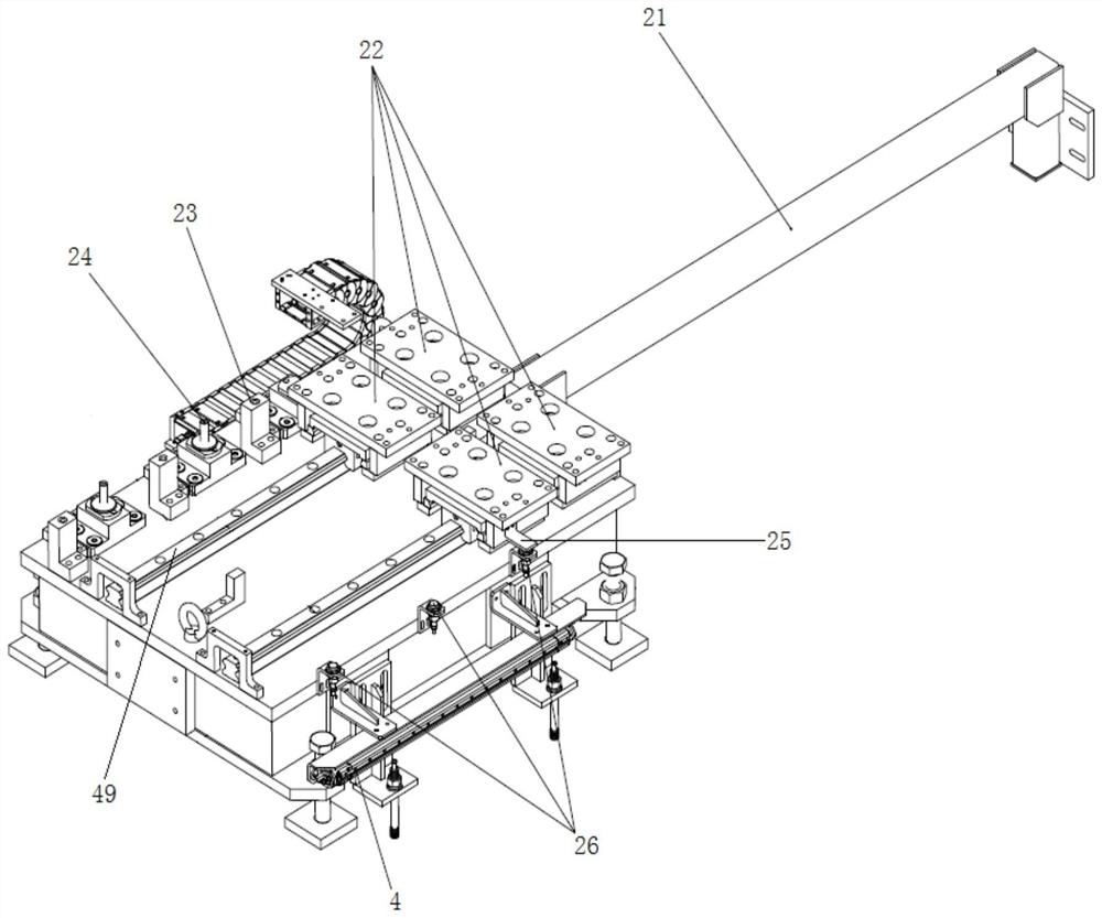
The invention discloses a top frame welding clamp, and belongs to the technical field of welding fixtures. The top frame welding clamp comprises a first truss beam and a second truss beam which is arranged horizontally with the first truss beam, the two ends of the bottom of the first truss beam and the two ends of the bottom of the second truss beam are connected with bases in a sliding mode, and positioning assemblies and locking assemblies are fixedly arranged on the bases. The positioning assemblies are used for positioning the sliding stroke of the first truss beam and the second truss beam and the locking assemblies are used for locking the first truss beam and the second truss beam after positioning. A sliding plate and a first driving mechanism for driving the sliding plate to slide on the first truss beam and the second truss beam are arranged at the corresponding ends of the first truss beam and the second truss beam, and a corner end pressing mechanism, a side top pressing mechanism and a side wall clamping mechanism are mounted on the sliding plate. The invention provides the top frame welding clamp which solves the technical problems that in the prior art, a top frame welding clamp is poor in universality, and clamping and fastening of a top frame cannot be truly achieved.

Description

technical field [0001] The invention relates to a top frame welding jig, which belongs to the technical field of welding jigs. Background technique [0002] Welding fixtures are widely used as fixtures to ensure the size of weldments, improve assembly accuracy and efficiency, and prevent welding deformation. At present, most of the existing top frame welding fixtures are fixed fixtures, which cannot be adjusted and clamped according to the different sizes of the top frame, and the versatility is poor, and because the fixed fixture is only equipped with a fixed support, although it can play a role in the top frame. The role of fixed support, but the clamping and fastening of the top frame cannot be realized in a real sense, which not only affects the welding efficiency, but also makes it difficult to ensure the structural accuracy of the top frame. Contents of the invention [0003] The purpose of the present invention is to overcome the deficiencies in the prior art, prov...

Claims


Application Information

Patent Timeline
Patent Type & Authority Applications(China)
IPC IPC(8): B23K37/00B23K37/04B23K101/24
CPCB23K37/00B23K37/0443B23K2101/24
Inventor 常立明
Owner 江苏鲁安特智能装备科技有限公司
Why Eureka
Try Eureka