
Test device and method for measuring ultimate bearing capacity of open caisson pipe pile composite anchorage

A technology of ultimate bearing capacity and test equipment, which is applied in the test of basic structure, construction, basic structure engineering, etc., can solve the problems of complex experimental operation, long cycle, complex design, etc., and achieve simple operation, low cost and simple measurement Effect

Inactive Publication Date: 2022-02-15
ZHEJIANG UNIV
View PDF7 Cites 0 Cited by
  • Summary
  • Abstract
  • Description
  • Claims
  • Application Information

AI Technical Summary

Problems solved by technology

In 1995 and 2005, Li Yongsheng and Li Jiaping conducted model tests on the north anchorage of the Jiangyin Yangtze River Bridge and the anchorage of the Ningbo Qingfeng Bridge respectively, but their anchorage models were based on the traditional gravity anchorage foundation, and the upper anchorage block The geometric shape of the prototype is completely similar to the prototype anchor, not only the design is complicated, but also the experimental operation is complicated and the cycle is long

Method used


Image

  • Test device and method for measuring ultimate bearing capacity of open caisson pipe pile composite anchorage
  • Test device and method for measuring ultimate bearing capacity of open caisson pipe pile composite anchorage
  • Test device and method for measuring ultimate bearing capacity of open caisson pipe pile composite anchorage

Examples


Embodiment 1

[0042] Embodiment 1, anti-pulling device.

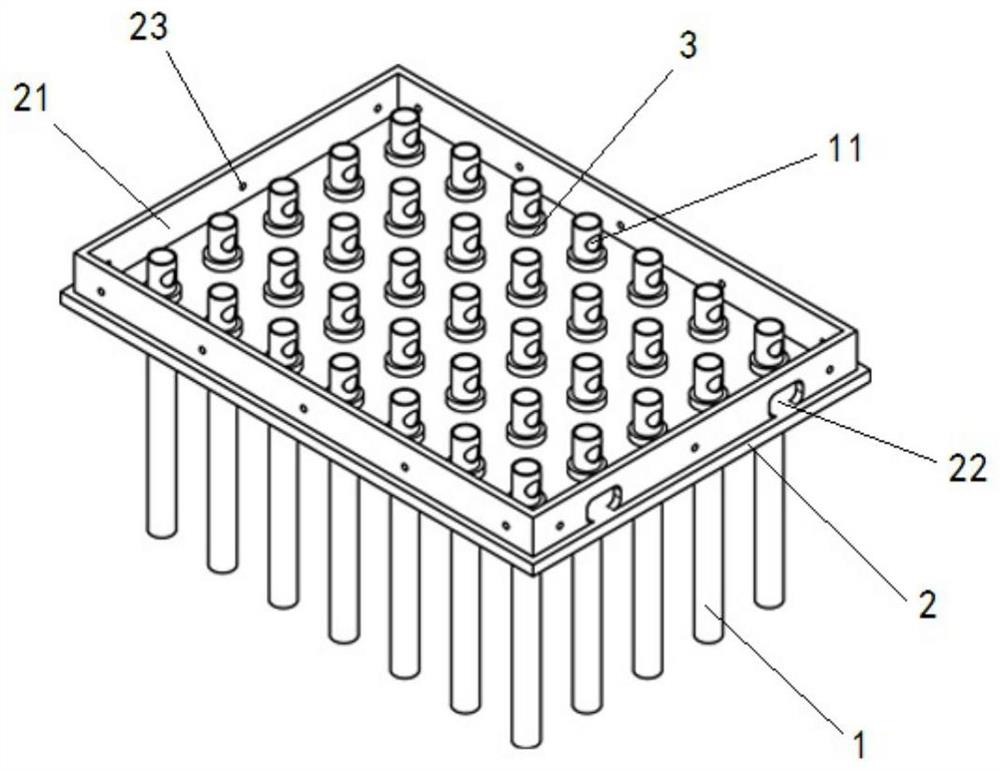
[0043] Refer to attached figure 1 , this embodiment provides an anti-pull device with pile group as the test object, its purpose is to prevent the pile group from detaching from the caisson floor during the process of being subjected to tension in the test, so as to ensure the accuracy and effectiveness of the pull-out test .

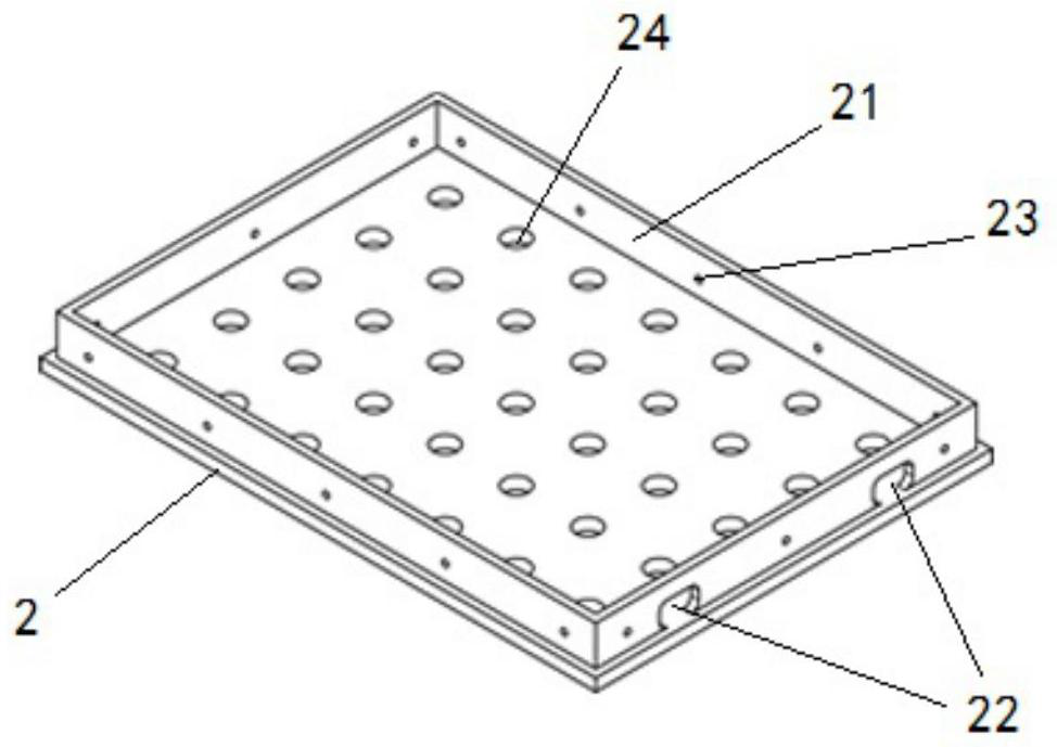
[0044] Such as figure 1 As shown in the figure, a plurality of pipe piles 1 are arranged according to certain rules to form a regular pile group, strain gauges are arranged outside the pipe piles 1, and pipe pile lead holes 11 are provided on the upper end side of the pipe piles 1; The upper part of the pile group is set with a caisson bottom plate 2, and the caisson bottom plate 2 is provided with a reserved pile hole 24, which corresponds to the size and position of the pipe piles 1 in the pile group, so that The pipe piles 1 can respectively penetrate into the reserved pile holes 21, and are fixedly conn...

Embodiment 2

[0048] Embodiment 2, anti-pressure device.

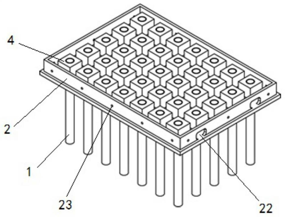
[0049] Refer to attached figure 2 , this embodiment further provides an anti-pressure device on the basis of embodiment 1.

[0050] In the pullout device of embodiment 1, high-strength gypsum 4 is poured on the top of the exposed pipe pile 1. When pouring high-strength gypsum 4, the caisson counterweight plate 5 must be covered before the high-strength gypsum 4 solidifies to ensure The top of each pipe pile 1 is subjected to the vertical load from the caisson counterweight plate 5, and the elevation error of the pipe pile 1 can be controlled within 2 mm (the caisson counterweight plate 5 is a part of the caisson structure and will be Further described in the Examples below).

[0051] Other implementation modes of this embodiment are the same as Embodiment 1.

Embodiment 3

[0052] Embodiment 3, counterweight structure.

[0053] Refer to attached Figure 4 , this embodiment further provides a counterweight structure on the basis of embodiment 2.

[0054] On the top of the anti-pressure device of embodiment 2, cover a caisson counterweight plate 5, the caisson counterweight plate 5 is fixedly connected with the upper surface of the side wall 21 by downward screws, the outer contour shape of the caisson counterweight plate 5 It is consistent with the outer contour of the side wall 21, and forms such as Figure 4 Flat sides shown.

[0055] The upper surface of the caisson counterweight plate 5 is fixedly provided with a caisson counterweight compartment 6, the size and number of grids of the caisson counterweight compartment 6 can be designed according to specific needs, and weights can be added to the caisson counterweight compartment 6, The purpose of the counterweight is to ensure that the size and center of gravity of the self-weight load of t...


PUM


Abstract

The invention provides a test device and method for measuring the ultimate bearing capacity of an open caisson pipe pile composite anchorage. The test device comprises a pile group composed of a plurality of pipe piles, wherein strain gauges are arranged outside the pipe piles, and pipe pile lead holes are formed in one sides of upper ends of the pipe piles; an upper portion of the pile group is sleeved with an open caisson structure, the top of the open caisson structure is provided with a displacement target and an extension rod, and an anti-pulling structure and a compression-resisting structure are arranged between the open caisson structure and the pile group. The device has advantages of being easy to disassemble, convenient to assemble, easy to operate, low in cost, capable of being recycled and the like, and various model test researches about the open caisson and the pile can be conveniently carried out.

Description

technical field [0001] The invention relates to a force analysis technology for a composite anchor, in particular to a test device and method for measuring the force of a caisson pile composite anchor. Background technique [0002] With the development of bridge construction, the span of the anchorage of the suspension bridge is continuously increasing, the volume of the anchorage foundation is continuously expanding, and the cost of the anchorage foundation is also rising exponentially. On this basis, a composite anchorage of caisson + pile is proposed It is hoped that the advantages of caissons and piles can be integrated to achieve the purpose of reducing the cost and shortening the construction period. [0003] At present, there are engineering examples using this kind of composite anchorage foundation at home and abroad, including Vincent Thomas Bridge (Ingham et al., 1997) and New Carquinez Bridge (Conte, 2008), but there are few studies on this kind of composite ancho...

Claims


Application Information

Patent Timeline
Patent Type & Authority Applications(China)
IPC IPC(8): E02D33/00
CPCE02D33/00
Inventor 赵小晴郭盼盼龚晓南段永乐
Owner ZHEJIANG UNIV
Features
  • Generate Ideas
  • Intellectual Property
  • Life Sciences
  • Materials
  • Tech Scout
  • Unparalleled Data Quality
  • Higher Quality Content
  • 60% Fewer Hallucinations
Learn More