Adjustable support for display equipment

A display device and an adjustable technology, which is applied in the direction of mechanical equipment, machines/brackets, supporting machines, etc., can solve problems such as premature air leakage failure, fatigue wear, deformation and fracture, and achieve safety, small overall thickness, and storage space small effect

Pending Publication Date: 2022-02-15
昆山泰如电子有限公司
View PDF4 Cites 0 Cited by
  • Summary
  • Abstract
  • Description
  • Claims
  • Application Information

AI Technical Summary

Problems solved by technology

For example, the structures of the brackets disclosed in patents with application numbers of 201710227401.4, 201820276409.X, 201820865573.4, and 201620738920.8 all consider and involve the above-mentioned problems to a certain extent. unit (that is, the structure of the spring / gas spring mentioned in the literature), the weight of the display device connected to the bracket is completely carried by the booster unit, and excessive reliance on the power of the booster unit will easily lead to premature air leakage failure of the booster unit. Fatigue, wear, deformation, fracture and other problems, so a solution that can solve the traditional problem and also overcome the failure of the booster unit is needed to prolong the service life of the equipment and avoid safety hazards caused by excessive exposure of the internal mechanical mechanism

Method used


Image

  • Adjustable support for display equipment
  • Adjustable support for display equipment
  • Adjustable support for display equipment

Examples


Embodiment 1

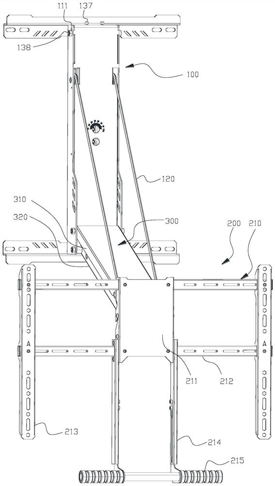
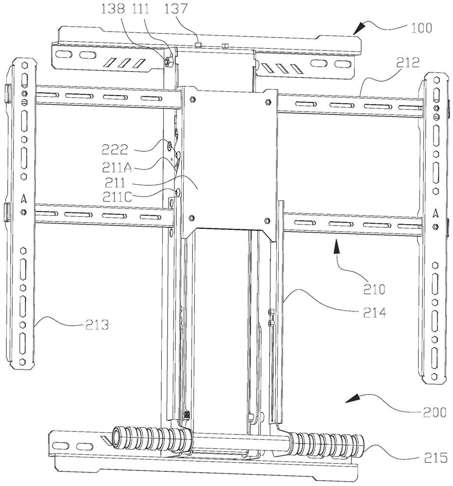
[0042] Reference attached figure 1 to attach Figure 10 , the adjustable bracket for the display device in this embodiment includes three parts: the mounting base 100, the connecting arm 300, and the hanger 200. The mounting base 100 is fixedly connected to the surface of the object, preferably a flat surface, such as a wall surface or cabinet surface. The hanger 200 is used for installing a display device, and the display device includes a general display and a tablet interactive device. Both ends of the connecting arm 300 are rotatably connected to the mounting base 100 and the hanger 200 respectively.

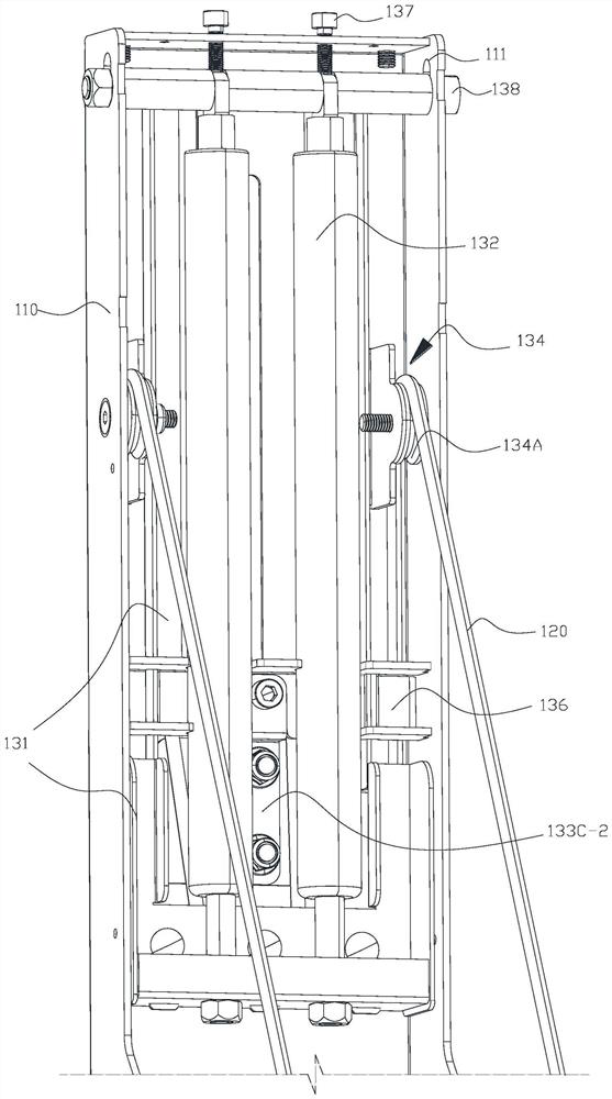
[0043] The mounting base 100 includes a casing 110, a lifting device 130, and a cable 120. The casing 110 is fixedly connected to the installation plane. The lifting device 130 is located inside the casing 110 to avoid user contact and exposure of the device, which is conducive to protecting the device and ensuring the use safety of the victim. The cable 120 is used for ...

Embodiment 2

[0056] The difference between this embodiment and Embodiment 1 is that one end of the two elastic members 132 is fixedly connected to the lower part of the lifting frame 131, and the other end is connected to the bottom of the housing 110, and the elastic members 132 provide downward pulling force to the lifting frame 131. , the length of the elastic member 132 in the first state is shorter than that in the second state. The position of the first chute 111 is adaptively arranged on the left and right sides of the lower part of the casing 110, the two ends of the connecting rod 138 are slidably connected to the first chute 111, and the two adjusting parts 137 pass through the bottom of the casing 110 to connect with the first chute 111. The rods 138 are offset, and the positions of the two adjusting parts 137 correspond to the positions of the two elastic parts 132 up and down.

[0057] When the support transitions from the first working state to the second working state, the e...

Embodiment 3

[0061] The difference between this embodiment and Embodiment 1 is that the movable pulley 135A is located above the second fixed pulley 134B, one end of the two elastic members 132 is connected to the upper part of the housing 110, and the other end is fixedly connected to the lifting frame 131, the elastic member 132 provides an upward pulling force to the lifting frame 131, and the length of the elastic member 132 in the first state is shorter than that in the second state.

[0062] When the support transitions from the first working state to the second working state, the lifting frame 131 moves downward, and the elastic member 132 is stretched.

[0063] The principle of this embodiment is the same as that of Embodiment 1. The structure of this embodiment can be imagined by those skilled in the art by combining the description of this embodiment with the drawings of Embodiment 1, so it is not shown in the drawings. The number of movable pulley and fixed pulley also can be ad...


PUM


Abstract

The invention discloses an adjustable support for display equipment, which comprises a mounting seat fixedly connected to the surface of an object, a hanging frame used for mounting the display equipment and a connecting arm with the two ends rotationally connected with the mounting seat and the hanging frame correspondingly, wherein the mounting seat is internally provided with a lifting device and an adjusting mechanism which are used for adjusting the folding and unfolding state of the hanging frame. The support is suitable for display equipment of various specifications, and the hanging frame is three-dimensionally adjustable relative to the mounting seat, so that the use requirement is met; a built-in power structure is beneficial to protecting the support and avoiding potential safety hazards; a user adjusts the position of the hanging frame relative to the mounting seat through operations such as pulling and pushing, the mounting and debugging operation is easy, and after the hanging frame is close to and folded relative to the mounting seat, the overall thickness of the support is small, and the occupied storage space is small; and the adjusting mechanism is arranged to solve the problem of premature failure of a power-assisted unit due to excessive dependence on the self power of the power-assisted unit.

Description

technical field [0001] The invention relates to a support, in particular to an adjustable support for a display device. Background technique [0002] With the progress of the times, displays have not only entered thousands of households, but are also used in many public places. At the same time, due to the increase of modern cultural activities, more and more types of displays are used, such as traditional display equipment, electronic interactive Equipment, electronic education whiteboard, etc., and the size of the display is increasing, making the difficulty of installing the display stand, the adjustable range, the adjustment method, and the safety of equipment use become important considerations when choosing a display stand. For example, the structures of the brackets disclosed in patents with application numbers of 201710227401.4, 201820276409.X, 201820865573.4, and 201620738920.8 all consider and involve the above-mentioned problems to a certain extent. unit (that is...

Claims


Application Information

Patent Timeline
Patent Type & Authority Applications(China)
IPC IPC(8): F16M13/02F16M11/04F16M11/18
CPCF16M13/02F16M11/046F16M11/18F16M2200/063F16M2200/048F16M11/048F16M11/38F16M2200/041F16M2200/028F16M2200/047F16M2200/065
Inventor 芮志华
Owner 昆山泰如电子有限公司
Why Eureka
Try Eureka