
Homopolar and same-slot three-phase permanent magnet motor

A permanent magnet motor, three-phase technology, applied in magnetic circuits, electrical components, electromechanical devices, etc., can solve the problems of inability to form multi-phase winding distribution, large power supply frequency and iron loss, and reduced motor torque pulsation. Power supply frequency and iron loss, reduce load torque fluctuation, easy to sinusoidal effect

Active Publication Date: 2022-02-15
NINGBO INST OF MATERIALS TECH & ENG CHINESE ACADEMY OF SCI
View PDF6 Cites 0 Cited by
  • Summary
  • Abstract
  • Description
  • Claims
  • Application Information

AI Technical Summary

Problems solved by technology

[0003] However, the pole-slot coordination of traditional permanent magnet motors adopts different number of slots / number of poles. In this way, when a motor with many poles and few slots is used, the power supply frequency and iron loss of the motor will be greater, and the distributed winding with few poles and multiple slots has a lower Power supply frequency and iron loss, but the winding end is long, the copper loss is low, and the cogging torque is large. The back EMF waveform of the motor: the back EMF waveform of the motor with few poles and many slots tends to be a trapezoidal wave, and the back EMF waveform of a motor with many and very few slots tends to be a triangular wave. These are not conducive to the reduction of motor torque ripple
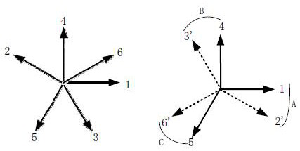
According to the slot electromotive force star diagram and the slot pitch angle formula, the traditional permanent magnet motor with the same pole and the same slot has only 0° and 180° due to the uniform distribution of the slots, which cannot form a multi-phase winding distribution.

Method used


Image

  • Homopolar and same-slot three-phase permanent magnet motor
  • Homopolar and same-slot three-phase permanent magnet motor
  • Homopolar and same-slot three-phase permanent magnet motor

Examples


Embodiment Construction

[0032] The present invention will be more fully understood from the following detailed description, which should be read in conjunction with the accompanying drawings. Detailed embodiments of the present invention are disclosed herein; however, it is to be understood that the disclosed embodiments are merely exemplary of the invention, which may be embodied in various forms. Therefore, specific functional details disclosed herein are not to be interpreted as limiting, but merely as a basis for the claims and as a teaching to one skilled in the art that, in fact, any suitably detailed embodiment may differ in any suitably detailed embodiment. The manner employs the representative basis of the present invention.

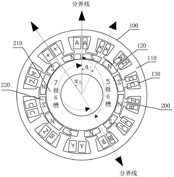
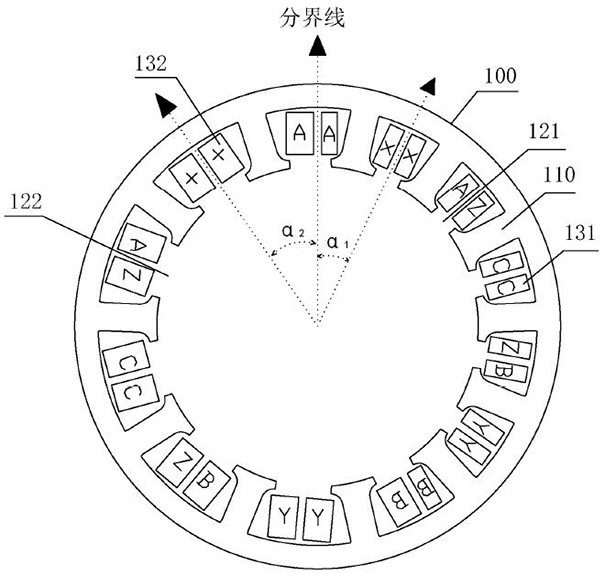
[0033] like figure 1 As shown, a three-phase permanent magnet motor with the same pole and the same slot disclosed in the embodiment of the present invention is specifically a three-phase permanent magnet motor with 12 poles and 12 slots (respectively defined as phase...


PUM


Abstract

The invention discloses a homopolar and same-slot three-phase permanent magnet motor. The permanent magnet motor comprises a stator and a permanent magnet rotor. The stator comprises a plurality of stator grooves, the permanent magnet rotor is concentrically arranged in the stator and comprises a plurality of permanent magnets, the number of magnetic poles displayed by the plurality of permanent magnets for air gaps is equal to the number of the stator grooves, and the stator grooves comprise first stator grooves and second stator grooves of different groove types. The number Z of the stator slots of each slot type is equal to 3n, and n is a positive integer greater than or equal to 1; the number of magnetic poles displayed by the permanent magnet corresponding to the first stator slot relative to the air gap is P1 = Z + k1, the pole slots are matched with P1 poles and Z slots, the number of magnetic poles displayed by the permanent magnet corresponding to the second stator slot relative to the air gap is P2 = Z-k1, the pole slots are matched with P2 poles and Z slots, and k1 is a positive integer greater than or equal to 1. The permanent magnet motor provided by the invention has lower power supply frequency and iron loss, higher efficiency and higher torque density, and is beneficial to reducing load torque fluctuation.

Description

technical field [0001] The invention belongs to the technical field of permanent magnet motors, and in particular relates to a three-phase permanent magnet motor with the same pole and the same slot. Background technique [0002] In order to reduce the torque fluctuation of the permanent magnet motor, there are mainly three methods on the motor body: 1) Changing the parameters of the permanent magnet. Changing the parameters of the permanent magnet mainly includes changing the shape of the permanent magnet, changing the pole arc coefficient, changing the placement position of the permanent magnet, the oblique pole, and the segmentation of the magnetic steel. 2) Change the armature parameters. There are mainly ways to change the armature parameters such as chute, opening auxiliary slot, and changing the slot width. 3) Reasonable pole-slot coordination, reasonable selection of the number of poles and slots can increase the fundamental frequency of the cogging torque of the m...

Claims


Application Information

Patent Timeline
Patent Type & Authority Applications(China)
IPC IPC(8): H02K1/16H02K1/2753H02K3/28
CPCH02K1/165H02K1/2753H02K3/28H02K2213/03
Inventor 陈进华杨九铜杨桂林张驰陈庆盈李荣
Owner NINGBO INST OF MATERIALS TECH & ENG CHINESE ACADEMY OF SCI
Learn More