

Transformer mounting base
A technology for installing bases and transformers
- Summary
- Abstract
- Description
- Claims
- Application Information
AI Technical Summary
Problems solved by technology
Method used
Image


Examples
Embodiment Construction
[0038] The following will clearly and completely describe the technical solutions in the embodiments of the present invention with reference to the accompanying drawings in the embodiments of the present invention. Obviously, the described embodiments are only some, not all, embodiments of the present invention. Based on the embodiments of the present invention, all other embodiments obtained by persons of ordinary skill in the art without making creative efforts belong to the protection scope of the present invention.
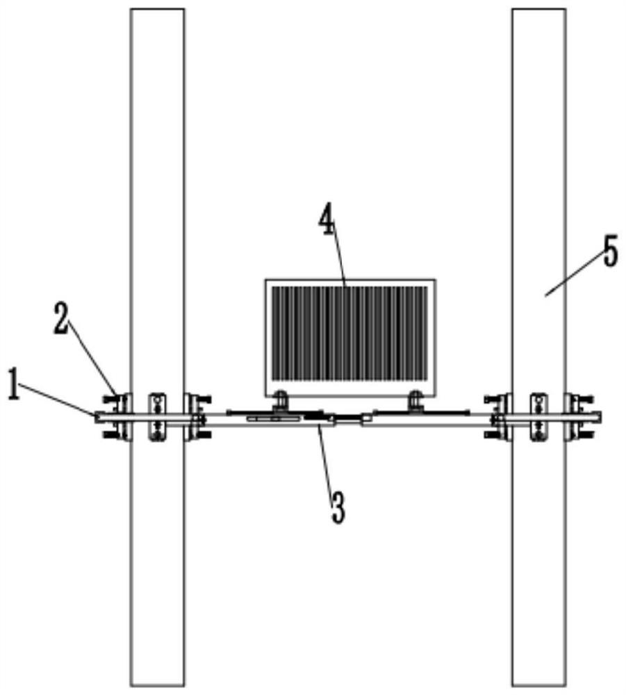
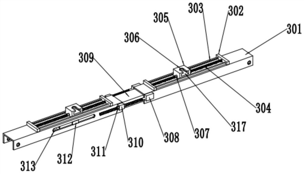
[0039] Such as figure 1 , 2, 12, a transformer 4 installation base, including two parallel beams 3, the two ends of the beams 3 are fixed to the utility poles 5 through the pole holding device, in order to increase the versatility, the application combines the beam 3 and the pole holding device Set as an adjustable structure, the beam 3 is mainly for adjusting the length and spacing to meet the different distances between the two utility poles 5 and the size ...
PUM
 Abstract
Description
Claims
Application Information